Solar panel tilt mechanism

Inactive Publication Date: 2005-02-01
HABER MICHAEL B
View PDF11 Cites 76 Cited by
  • Summary
  • Abstract
  • Description
  • Claims
  • Application Information

AI Technical Summary

Benefits of technology

Accordingly, in one broad form of the invention there is provided a solar panel tilt mechanism for an array of solar panel assemblies; said mechanism adapted to take account of solar and wind conditions and further adapted to tilt in unison all panel assemblies forming said array of solar panels assemblies; said tilt mechanism incorporating individual panel tilt means associated with each individual panel assembly of said array of panels;

Problems solved by technology

Particularly where each array becomes itself large in area the complexity and hence cost of ti

Method used


Image

  • Solar panel tilt mechanism
  • Solar panel tilt mechanism
  • Solar panel tilt mechanism

Examples


Embodiment Construction

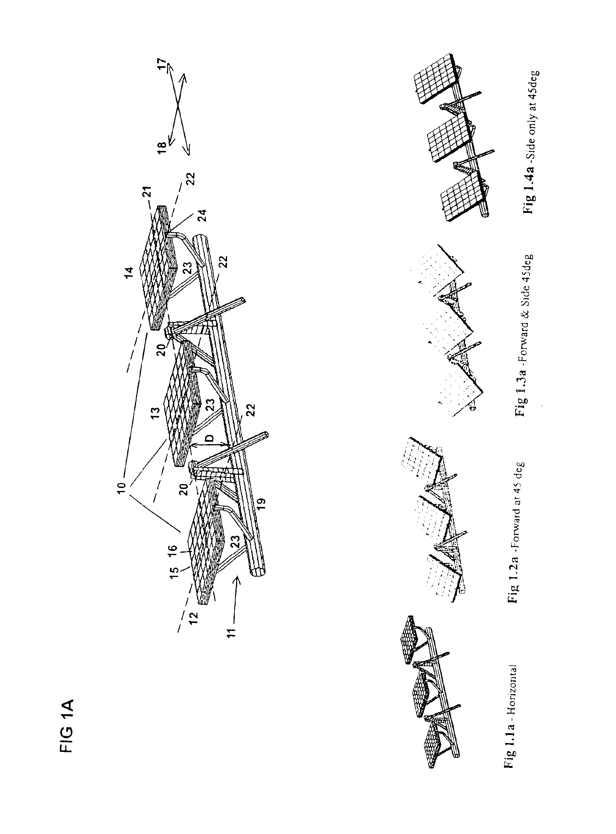
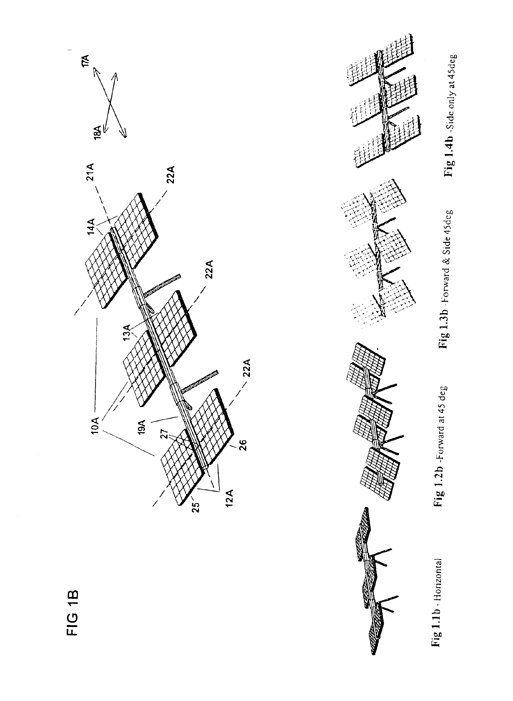
Initially, with reference to FIG. 1A there is illustrated a solar panel array 10 incorporating a tilt mechanism 11 according to a first preferred embodiment of the present invention.

In this instance the solar panel array 10 comprises an array of three panel assemblies12, 13, 14. In this instance each panel assembly comprises a substantially flat panel is with an array of solar cells 16 mounted on the top thereof under a protective layer and facing in an upward direction relative to the solar panel assembly 10.

The tilt mechanism 11 supports all of the panel assemblies 12, 13, 14 in a manner; which permits their tilting in unison about, in this instance, a first tilt axis 17 and a second tilt axis 19. In this instance the first tilt axis 17 is aligned with the longitudinal axis of primary support member 19 but, by virtue of support points 20, is displaced from the axis of primary support member 19 a vertical distance D thereby placing first tilt axis 17 aligned substantially, in this ...


PUM


Abstract

A tilt mechanism associated with a solar panel assembly whereby effort required to tilt panel assemblies comprising the solar panel assembly is reduced or minimized by appropriate placement of first and second tilt axes with respect to the center of mass and/or center of pressure of the panel assemblies due to wind. These arrays are suitable for use on mobile or static installations. The tilt mechanism is suited for harnessing wind energy if the panels are suitably shaped.

Description

The present invention relates to a solar panel tilt mechanism and, more particularly, to such a mechanism adapted for use with an array of solar panelsBACKGROUNDNowadays solar cells are finding application in many fields of endeavour because the power output per unit weight and per unit cost has been steadily increasing.Nonetheless, it is still the case that a relatively large solar collection area is required to obtain sufficient power output for many applications.Array area can be minimized for a given power output if it is possible to tilt the array in at least one dimension and, more preferably, in two dimensions so that the array tracks the sun with the aim being to maximize the amount of time that solar radiation is incident perpendicular to the plane of the solar cells making up any given array.Particularly where each array becomes itself large in area the complexity and hence cost of tilting mechanisms can begin to work against the economics of adopting a sun tracking mechan...

Claims


Application Information

Patent Timeline
IPC IPC(8): F24J2/40F24J2/54F24J2/00
CPCF24J2/405F24J2/5424H02S20/00F24J2002/0084Y02E10/47Y02E10/50F24J2002/5468F24S30/455F24S50/60F24S2020/16F24S2030/136H02S20/10H02S20/32
Inventor HABER, MICHAEL B.
Owner HABER MICHAEL B
Why Eureka
Try Eureka