Drive mechanism for oscillatory abrasion and polishing tool

a technology of abrasive bit and drive mechanism, which is applied in the direction of manufacturing tools, edge grinding machines, dental surgery, etc., can solve the problems of abrasive bit recoiling or running away from the nail, difficult for an untrained individual to control such units, and poor acceptance of prior units by consumers, so as to avoid the spread of infection, and achieve the effect of economics and reliably implementation

Inactive Publication Date: 2005-02-01
CROSSTEX INT INC
View PDF25 Cites 24 Cited by
  • Summary
  • Abstract
  • Description
  • Claims
  • Application Information

AI Technical Summary

Benefits of technology

It is therefore an object of the present invention to provide a disposable tool assembly having a driving mechanism that imparts oscillatory rotary motion to a device mounted on the assembly and to achieve this with a structure that can be economically, and reliably implemented in plastic to allow for disposability and the attendant avoidance of the spreading of infection.

Problems solved by technology

These prior units have not been well accepted by consumers for several reasons.
The very high speeds and the sensible torque reaction have made it quite difficult for an untrained individual to control such units.
The tendency is for the abrasive bit to recoil or to run itself away from the nail.
While this is feasible when the units are used by a second person, it is clearly unsuitable when it is desired to use the unit for self-manicure.
Using the rotating device with a bur (drill bit) can be a dangerous device when used improperly.
These high-speed, small-diameter bits tend to groove or to “scallop” the nail if they are presented against the nail with too much force or for too long a time.
Therefore, any distraction or inattention frequently would result in the formation of a small-diameter arc-shaped deformation of the nail, in contrast to the desired sculpturing being attempted.
In the course of the invention, it has been discovered that many accidents occur namely by cutting into the cuticle area, which can lead to some serious infections.
In addition it has also been discovered that fingernail / cuticle infections are on the rise because of improper use of these polishing / sanding drills and the fact that these drills are rarely sterilized properly.

Method used


Image

  • Drive mechanism for oscillatory abrasion and polishing tool
  • Drive mechanism for oscillatory abrasion and polishing tool
  • Drive mechanism for oscillatory abrasion and polishing tool

Examples


Embodiment Construction

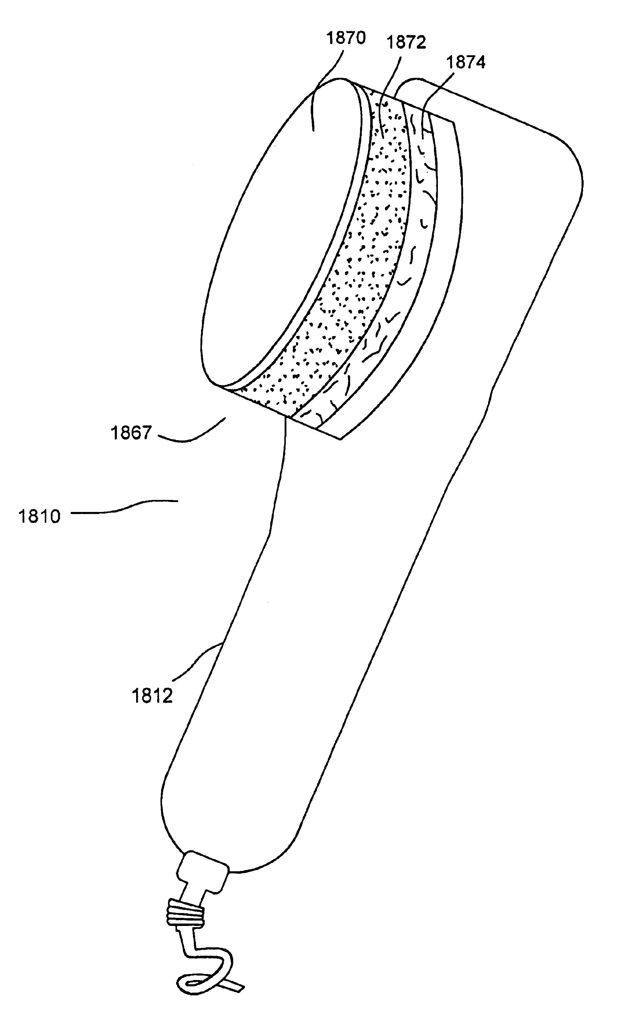
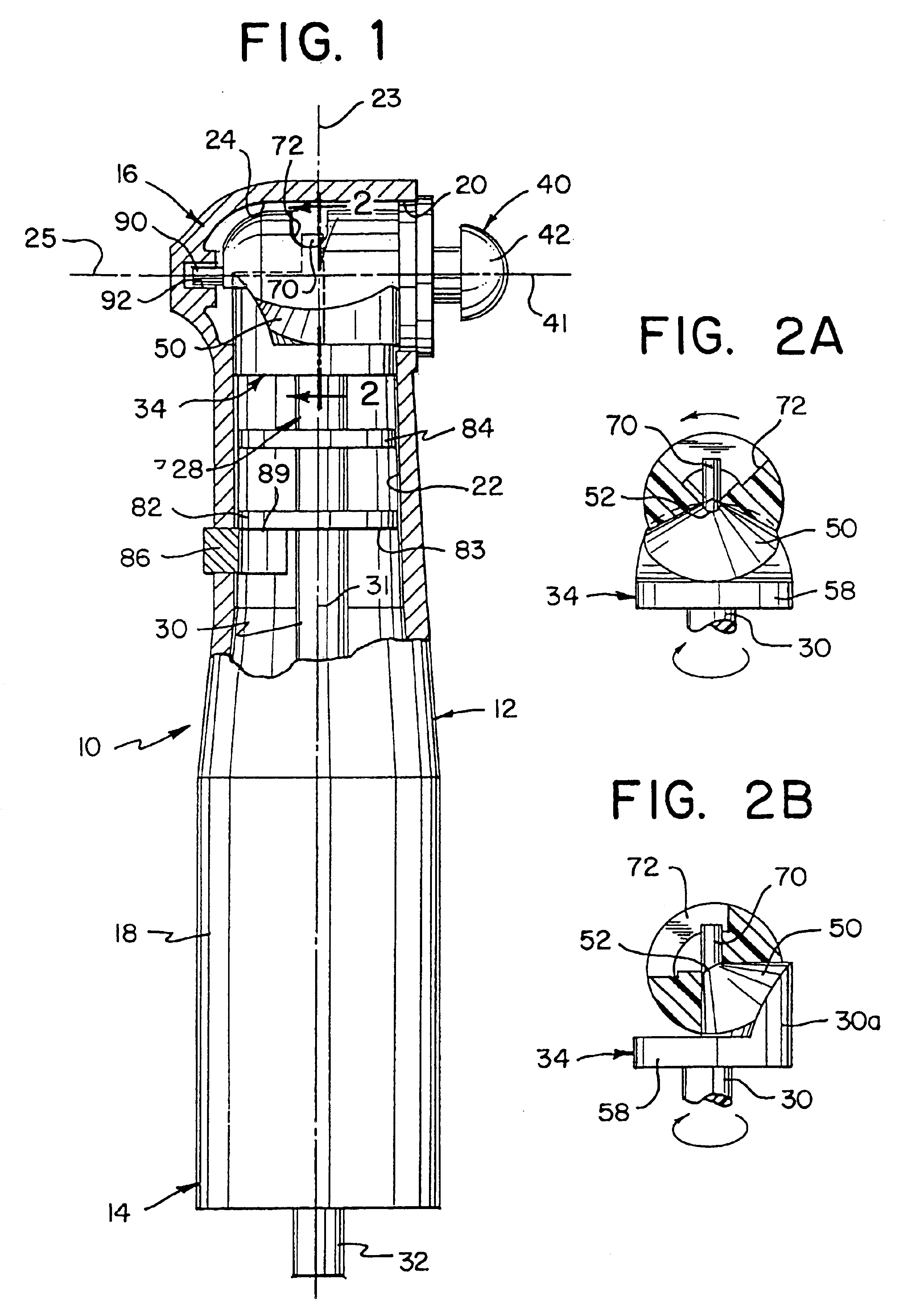
A tool assembly 10, formed in accordance with the principles of the present invention, is shown in FIG. 1. Tool assembly 10 includes a housing 12 having a proximal end 14 and a distal end 16, with main body portion 18 extending therebetween. Proximal end 14 is coupled to a tool hand piece (not shown) known in the art. Distal end 16 has a side opening 20 at which a desired device (not shown) is coupled. However, the preferred embodiment of the tool assembly shown in the Figures is a polishing brush which would be appropriately adjusted for use in buffing nails, or for polishing shoes or furniture and the like. Alternative embodiments replacing the brush with an abrasive surface are also contemplated. It will be understood that any appropriate tool piece known in the art may be used.

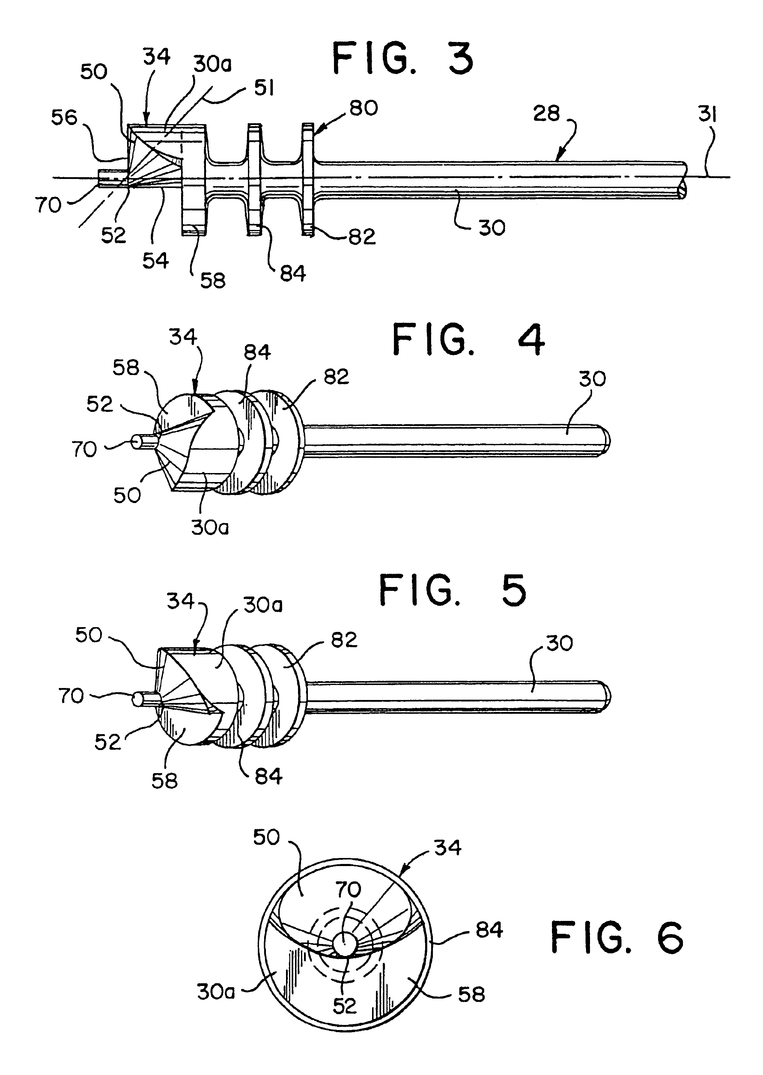
Housing 12 is hollow such that first and second channels 22, 24 are formed therein for housing driving mechanism 28. First, longitudinal channel 22 is formed within main body portion 18 and extends from pr...


PUM


Abstract

A transmission for changing rotary motion into angularly reciprocating motion and adapted to be mounted on the output end of a power unit of the type having a rotary drive output and used to drive a tool. The transmission is comprised of a support member, a driving resinous member supported by the support member for rotary motion, and a driven resinous member supported by the support member for reciprocating angular movement by the support member. The transmission subassembly is formed by the driving resinous member, driven resinous member and support member and adapted to be mounted on the output end of the power unit with a rotary drive output mechanically coupled to the driving resinous member. A driving cam surface is disposed on a portion of the driving resinous member. A driven cam surface is disposed on a portion of the driven resinous member. The driving cam surface is in contact with the driven cam surface during at least a portion of the cycle of rotation of the driving cam surface. The driven cam surface is configured and dimensioned to be driven by the driving cam surface in a positive angular direction during one part of the cycle and is driven by the driving cam surface in a negative angular direction during another part of the cycle. Angularly reciprocating motion is thereby imparted to the tool as the driving cam surface and driven cam surface engage each other. The tool is particularly advantageous when used in connection with motorized manicure tools, polishing devices, and dermabrasion devices.

Description

STATEMENT REGARDING FEDERALLY SPONSORED RESEARCH OR DEVELOPMENTNot ApplicableBACKGROUND OF THE INVENTION1. Technical FieldThe present invention relates to a tool assembly having a head that imparts oscillatory motion to a desired device coupled to the assembly. More particularly, the present invention relates to a drive mechanism for a tool assembly, the drive mechanism having a rotating drive shaft that engages a first end of a driven shaft to rotate the driven shaft in an oscillatory manner. The inventive tool assembly is particularly advantageous when used in connection with massaging, dermabrasion, nail buffing and sculpting, woodworking and polishing assemblies.2. Description of the Related ArtBrushes have been used for many years to polish, clean and abrade a wide variety of substrates. These brush products typically have a plurality of bristles that contact the substrate. U.S. Pat. Nos. 5,152,917 and 5,304,223 (Pieper et al.) teach coated abrasive articles comprising precisel...

Claims


Application Information

Patent Timeline
Patent Type & Authority Patents(United States)
IPC IPC(8): A61C17/00A61C1/00A61C1/18A61C1/08A61C1/07
CPCA61C1/07A61C17/005A61C1/185
Inventor POSTAL, ROBERT T.WALLACE, ROBERT P.
Owner CROSSTEX INT INC
Why Eureka
Try Eureka