Wellbore power generating system for downhole operation

a power generation system and wellbore technology, applied in the direction of borehole/well accessories, magnetic circuit rotating parts, borehole/well accessories, etc., can solve the problems of obstructing the well, affecting the long-term usefulness of modern-day production operations, etc., to achieve the effect of long-term li

Inactive Publication Date: 2005-02-01
HALLIBURTON ENERGY SERVICES INC
View PDF14 Cites 108 Cited by
  • Summary
  • Abstract
  • Description
  • Claims
  • Application Information

AI Technical Summary

Benefits of technology

An advantage of the present invention is that it provides full access to the components in the wellbore and does not restrict the diameter of the production tubing, allowing tools to pass through the wellbore without clogging.
Another advantage of the present invention is that the rotation member provides a downhole power generation system with a relatively long life compared to umbilical systems and batteries.
Still another advantage of the present invention is the ability to provide downhole electrical power for long periods of time.

Problems solved by technology

While such downhole power systems have proven useful, they do not meet the long term power needs of modern day production operations.
For example, while the use of an umbilical is suitable for providing power and data communications to devices, the practical difficulties related to their installation and maintenance limits their long term usefulness.
At the same time, umbilical systems can interfere with and obstruct the well, production tubing, and other down hole structures by restricting passage of tools and other components into the wellbore.
The use of wireless telemetry with batteries has been contemplated, but such systems suffer from an inability to provide useful levels of power or sustain power over long periods of time.

Method used


Image

  • Wellbore power generating system for downhole operation
  • Wellbore power generating system for downhole operation
  • Wellbore power generating system for downhole operation

Examples


Embodiment Construction

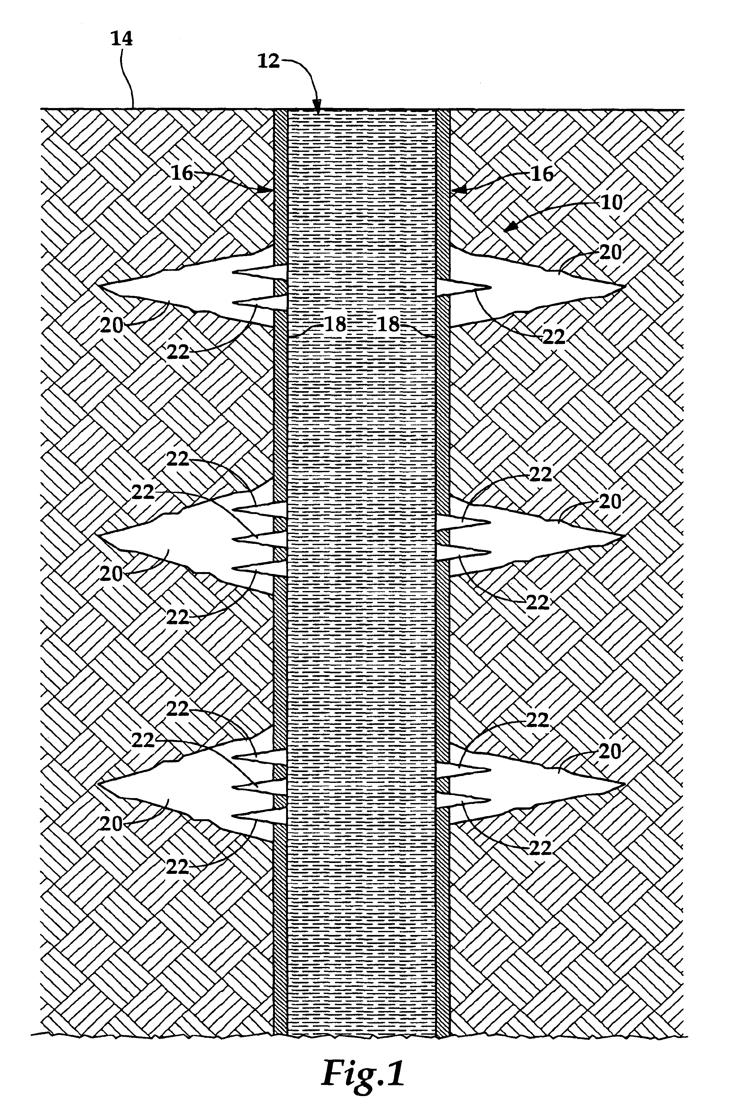
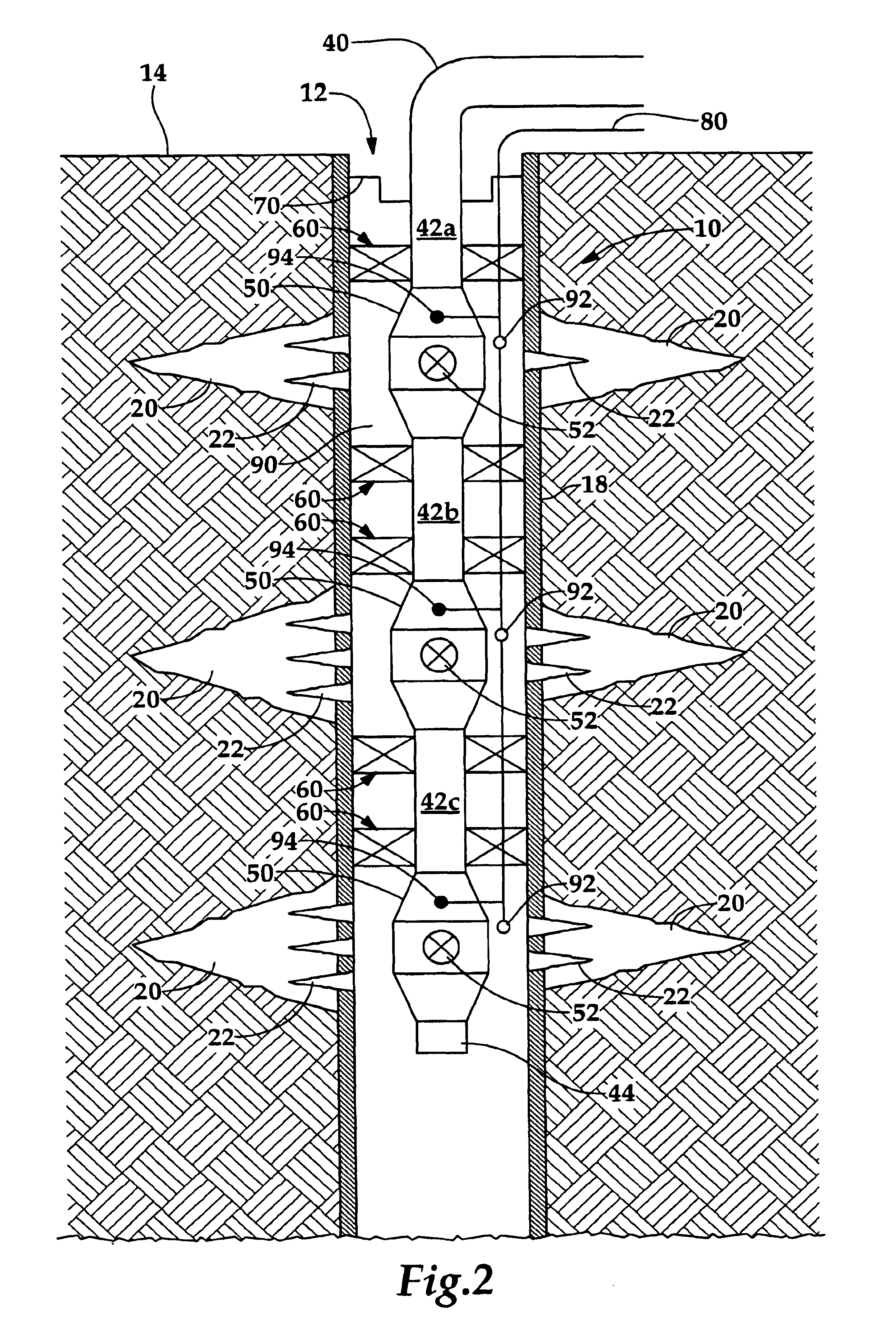
The present invention provides a system for generating power within a wellbore and, more specifically, a downhole operation utilizing production tubing to remove fluids, such as crude oil, from one or more production zones underneath the earth's surface. With reference now to the figures, and in particular to FIG. 1, therein is shown a typically downhole operation, denoted generally as 10, in which the present invention may be utilized. In essence, the downhole operation 10 provides an excavation underneath the earth's surface 14 which is created using well known techniques in the energy industry. The operation 10 includes a wellbore 12 with wall 16 lined with casing 18 which has a layer of cement between the wellbore 12 and the casing 18 such that a hardened shell is formed along the interior of the wellbore 12. For convenience, the singular and plural of a term (“passageway” and “passageways”, “zone” or “zones”, “sleeve” or “sleeves”, “packer” or “packers”, etc.) will be used inte...


PUM


Abstract

A power generating system (100) for a downhole operation (10) having production tubing (40) in a wellbore (12) includes a magnetized rotation member (110) coupled to the wellbore (12) within the production tubing (40), the rotation member (110) having a passageway (112) through which objects, such as tools, may be passed within the production tubing (40). Support braces (170, 172) couple the rotation member (110) to the production tubing (40) and allow the rotation member (110) to rotate within the production tubing (40). Magnetic pickups (150, 152) are predisposed about the rotation member (110) within the wellbore (12) and a power conditioner (200) is provided to receive currents from the magnetic pickups (150, 152) for storage and future use. The rotation member (110) rotates due to the flow of fluid, such as crude oil, through the production tubing (40) which causes the rotation member (110) to rotate and induce a magnetic field on the magnetic pickups (150, 152) such that electrical energy is transmitted to the power conditioner (200), the power conditioner able to store, rectify, and deliver power to any one of several electronic components within the wellbore (12).

Description

TECHNICAL FIELDThe present invention relates in general to downhole operations and the production of electrical power within an oil producing wellbore. More specifically, the invention relates to a system for generating power from fluid flow through production tubing in a wellbore. Still more specifically, the invention relates to such a system using a magnetized rotation member that operates on principles similar to a Darrieus rotor and that is capable of generating a magnetic field to produce useable power.BACKGROUND OF THE INVENTIONDownhole well applications, such as those used to extract crude oil from one or more production zones underneath the earth's surface, often require downhole power in order to operate components such as pressure and temperature sensors in the well. Current systems requiring downhole power include intelligent wells and permanent gauge installations where sensors or actuators are used in order to operate chokes and restrict fluid flow into a well at diffe...

Claims


Application Information

Patent Timeline
Patent Type & Authority Patents(United States)
IPC IPC(8): E21B41/00F03B13/00
CPCE21B41/0085F03B13/00H02K7/1823Y02B10/50F05B2220/60F05B2220/20
Inventor SCHULTZ, ROGER L.FRIPP, MICHAEL L.WATSON, BROCK W.
Owner HALLIBURTON ENERGY SERVICES INC
Why Eureka
Try Eureka