
Method of triggering a vehicle occupant restraining device

a technology for restraining devices and occupants, which is applied in the direction of pedestrian/occupant safety arrangements, vehicle components, tractors, etc., can solve the problems of lack of conformity of the response behavior of the sensor, difficulty in distinguishing between actual crashes, and extreme stress on the vehicle, etc., and achieves the effect of higher crash severity and higher crash severity

Inactive Publication Date: 2005-02-01
BAYERISCHE MOTOREN WERKE AG
View PDF16 Cites 6 Cited by
  • Summary
  • Abstract
  • Description
  • Claims
  • Application Information

AI Technical Summary

Benefits of technology

This and other objects and advantages are achieved by the method according to the invention wherein a timer is started when a first low crash severity occurs. In this case, it will not be necessary to differentiate between the above-mentioned very stressful drive and a crash, so that it is permissible for the timer to be triggered during such a drive. The crash event will be clearly recognized only by an additional triggering condition, in the form of the occurrence of a higher crash severity.
The triggering time for the restraining device is again determined by the timer. The restraining device will be triggered at the end of the running time of the timer if the higher severity of the crash has occurred during this running time. As an alternative, if the higher crash severity does not occur before the end of the running time, triggering takes place thereafter, as soon as a higher crash severity does occur, provided only that t

Problems solved by technology

In this triggering algorithm, it is difficult to distinguish between an actual crash, and extreme stress to the vehicle, which occurs for example, during a fast drive along a gravel and pothole covered route.
An additional fact is the lack of conformity of the response behavior of the sensor in the case of different vehicles of the same manufacturer and of the same type.

Method used


Image

  • Method of triggering a vehicle occupant restraining device
  • Method of triggering a vehicle occupant restraining device

Examples


Embodiment Construction

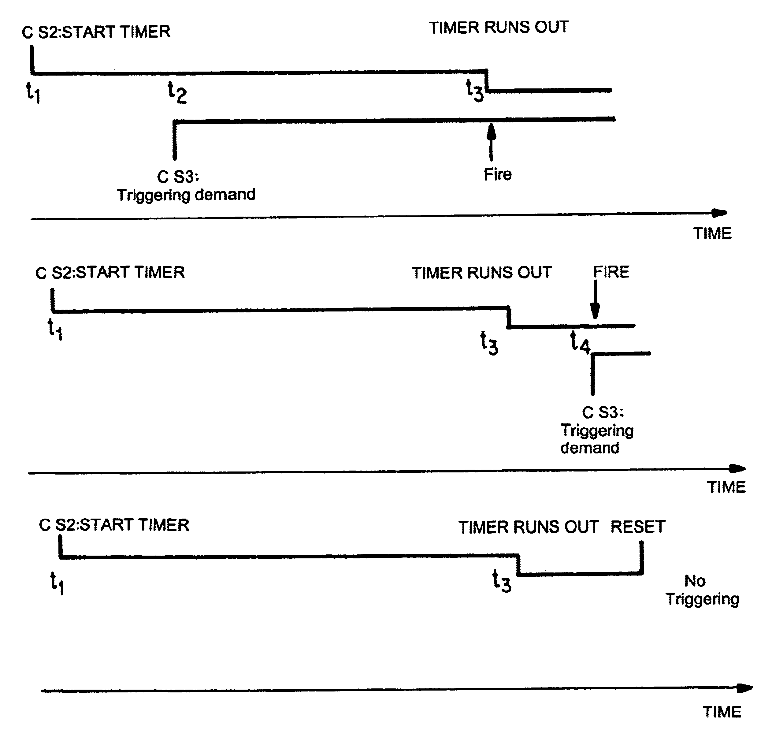
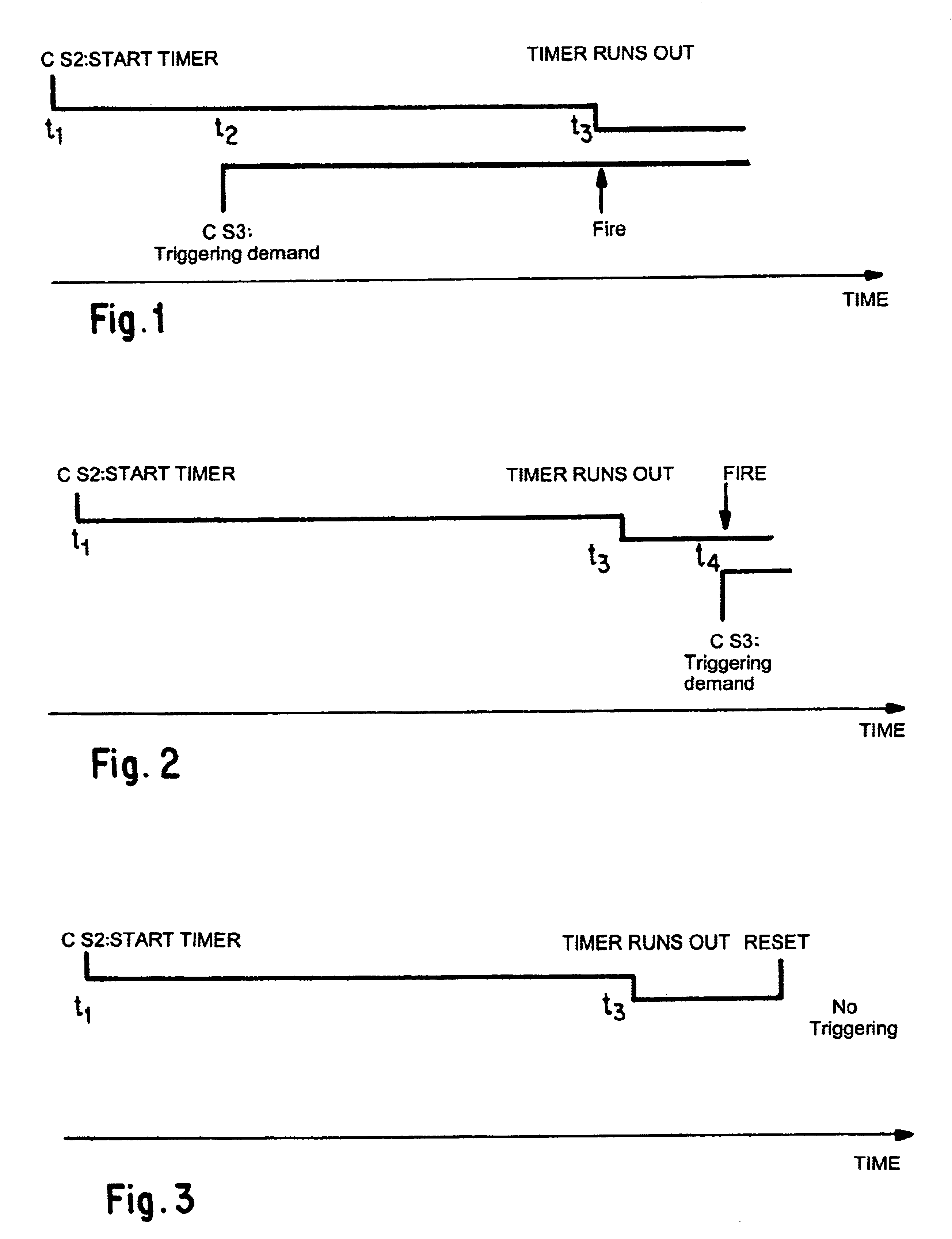
In FIG. 1, a crash severity (“CS”) whose value CS2 is above a value of CS1 that occurs in the normal driving operation, results in the start of a timer (not shown) at time t1. During a running time of, for example, 10 ms, the timer counts down from its initial value. However, before the end (t3) of this running time (that is, before the count reaches zero at time t3), a second condition (a higher crash severity CS3) occurs (time t2) for the triggering of the restraining device. The ignition circuit (not shown) for the restraining device is ignited (“fire”) thereafter, at the end of the running time of the timer.

In FIG. 2, CS2 results, once again, in the start of the timer at time t1. The running time ends at time t3, and the timer remains at 0 ms waiting time. Thereafter, at time t4, the second condition occurs in the form of the higher crash severity CS3. The ignition circuit is triggered immediately at time t4 (“fired”) because the timer has already run out.

Finally, in FIG. 3, CS2...


PUM


Abstract

In a method of triggering a vehicle occupant restraining device, at least one sensor signal generated by a crash sensor is supplied to an analyzing device, which determines the crash severity, and a time for the triggering of the restraining device based on the crash severity. When a first low crash severity occurs, a timer is started and the restraining device is triggered by the analyzing unit only when a higher crash severity is reached during the running time of the timer.

Description

BACKGROUND AND SUMMARY OF THE INVENTIONThis application claims the priority of German patent document 101 47 732, filed 27 Sep. 2001, the disclosure of which is expressly incorporated by reference herein.The invention relates to a method of triggering a vehicle occupant restraining device.In a method of this generic type disclosed in U.S. Pat. No. 5,999,871, the severity of the crash is determined by means of an acceleration signal which is supplied by an acceleration sensor. If this acceleration signal reaches a defined threshold value, it is deemed to reach the decisive severity of a crash. The restraining device—here, a first stage of an air bag—is triggered immediately. In this triggering algorithm, it is difficult to distinguish between an actual crash, and extreme stress to the vehicle, which occurs for example, during a fast drive along a gravel and pothole covered route. Accelerations occur in the latter case which are comparable to those of an actual crash. In order not to ...

Claims


Application Information

Patent Timeline
IPC IPC(8): B60R21/01
CPCB60R21/013B60R2021/01265
Inventor LINK, ANDREAWATZKA, WILLIBALDMAURER, CHRISTIANNIESS, MICHAELURBAHN, JAN
Owner BAYERISCHE MOTOREN WERKE AG
Learn More