Optical fiber connector with a base end threaded ferrule

a technology of optical fiber connector and ferrule, which is applied in the direction of optics, instruments, optical light guides, etc., can solve the problems of optical loss, optical transmission rate reduction, and complete elimination of optical loss, and achieve the effect of reliabl

Inactive Publication Date: 2005-02-01
SUNCALL +1
View PDF8 Cites 89 Cited by
  • Summary
  • Abstract
  • Description
  • Claims
  • Application Information

AI Technical Summary

Benefits of technology

The object of the present invention is to provide an optical fiber connector for making high-precision optical connections between optical fibers wherein a rotation-restricting slide mechanism is disposed toward the base end of

Problems solved by technology

This leads to optical loss and a reduction in optical transmission rates.
As a result, it is difficult to eliminate completely optical loss at the connection surface between the optical fibers, thereby reducing the optical transmission rate.
Since the ferrule cannot be adjusted while observing from

Method used


Image

  • Optical fiber connector with a base end threaded ferrule
  • Optical fiber connector with a base end threaded ferrule
  • Optical fiber connector with a base end threaded ferrule

Examples


Embodiment Construction

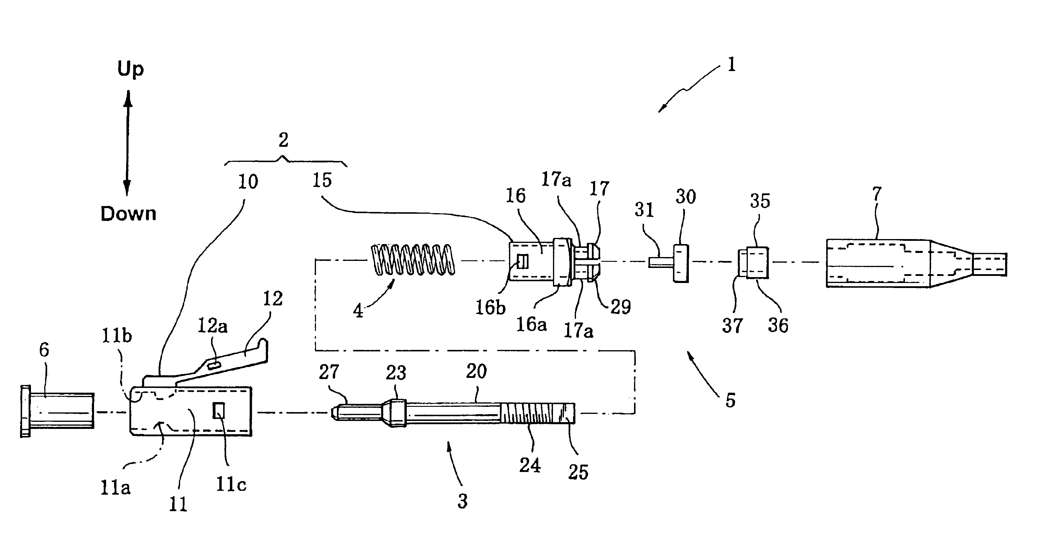
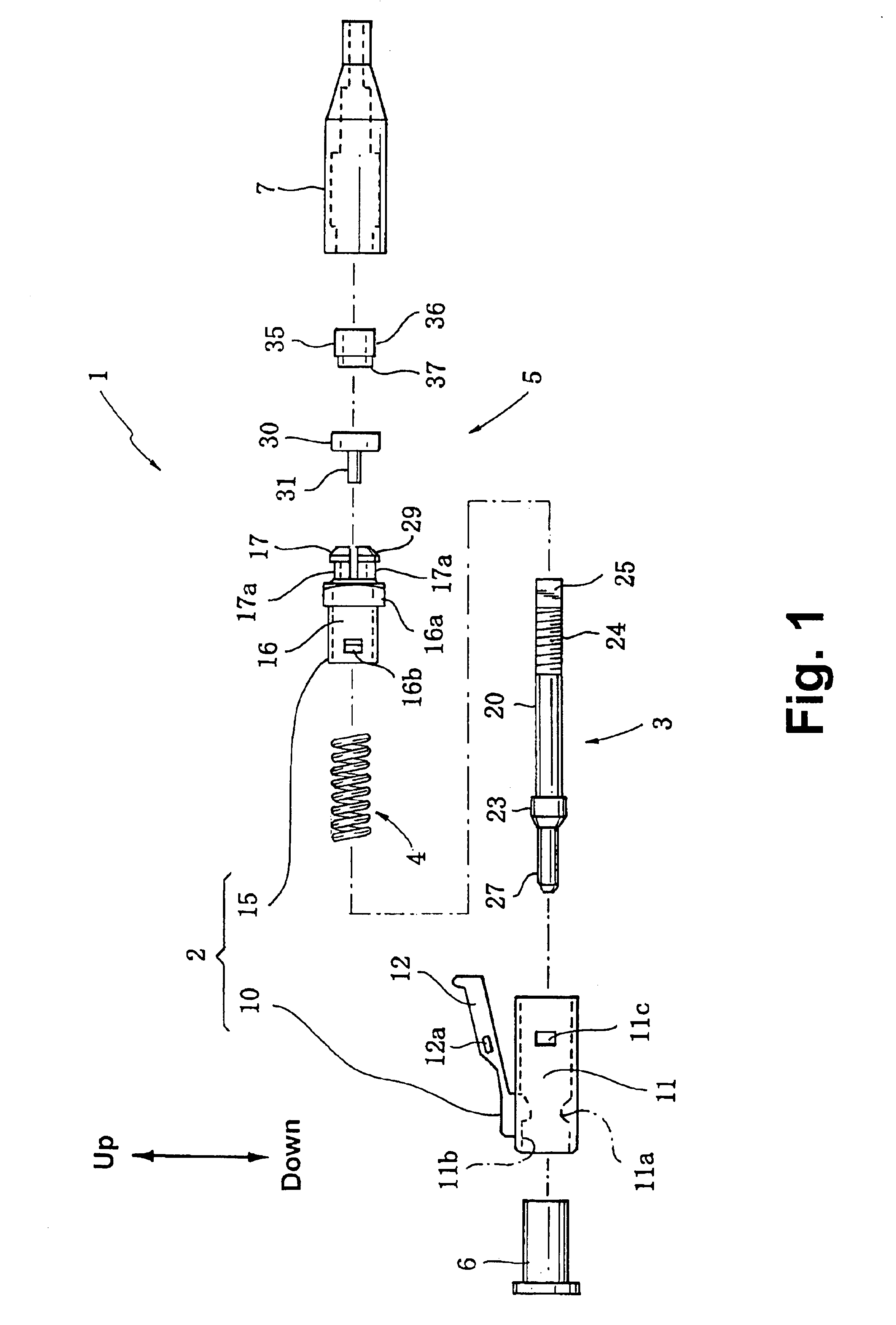
The embodiments of the present invention will be described with reference to the accompanying drawings. In this embodiment, the present invention is implemented for an optical fiber connector attached to the leading end of an optical fiber to provide an optical connection between optical fibers via an adapter. The up and down directions referenced in the following description are shown in FIG. 1.

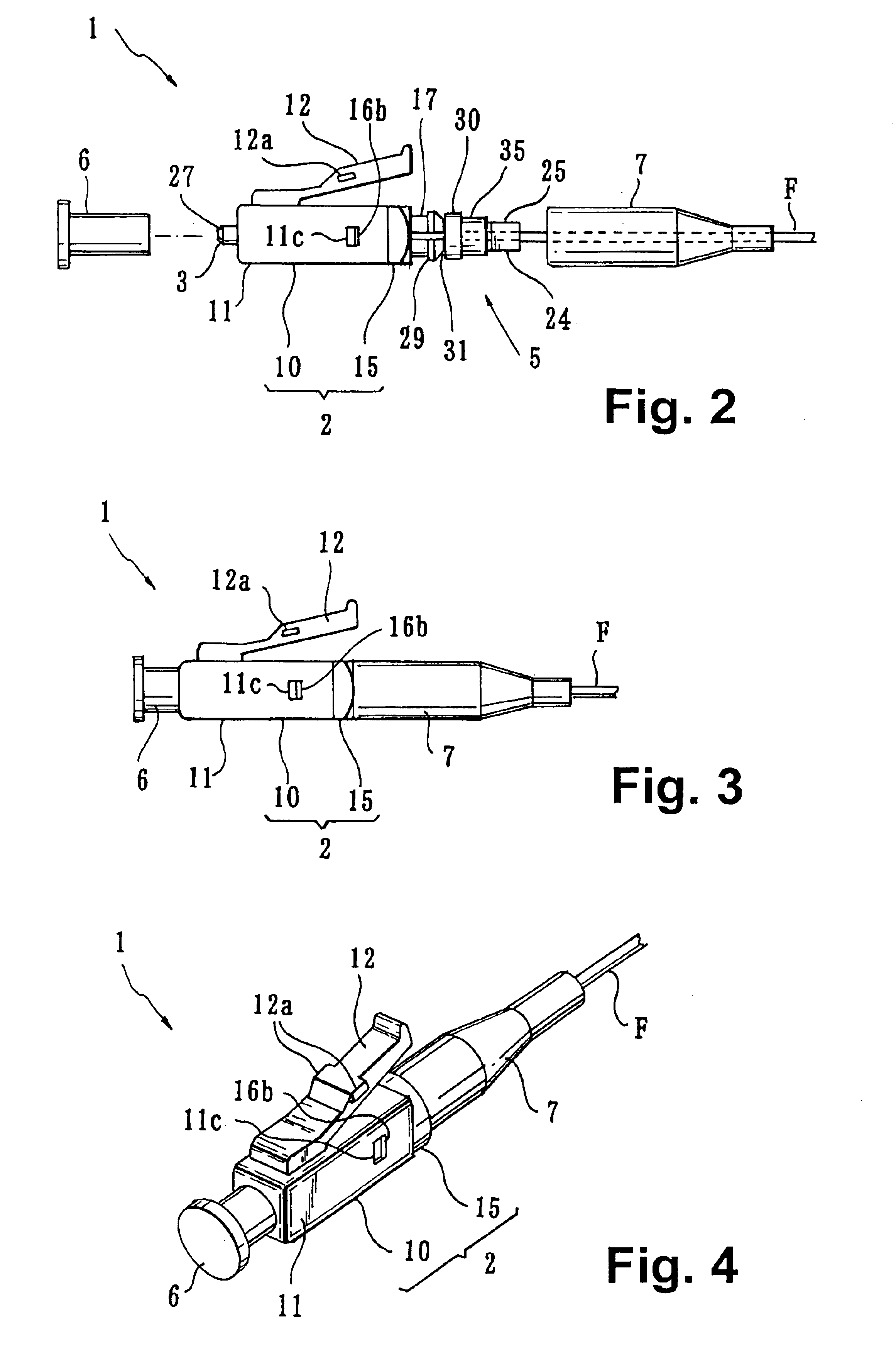
As shown in FIGS. 1-5, an optical fiber connector 1 (hereinafter referred to as the connector 1) comprises: a housing 2 that can be attached to or removed from an adapter A (as shown in FIG. 17); a ferrule 3 supporting a cladding portion F1 at the leading end of an optical fiber F inserted through the ferrule 3 (as shown in FIG. 8) housed in the housing 2 so that it can move along the axis and so that it can rotate during the assembly process; a compression coil spring 4 mounted inside the housing 2 and biasing the ferrule 3 along the axis toward the leading end; and a rotation-restricting s...


PUM


Abstract

The present invention provides an optical fiber connector for making high-precision optical connections between optical fibers. During assembly, a ferrule is rotationally adjusted around its axis 360° without stepping. The assembly, including this rotational adjustment, can be performed easily and reliably.
An optical fiber connector 1 comprises: a housing 2 that can be mounted on and removed from an adapter A; a ferrule 3 through which a cladding portion F1 at the end of an optical fiber F is inserted is rotatably housed in the housing 2 so that it can move along the axial direction; a compression coil spring 4 biasing the ferrule 3 in the axial end direction; and a rotation-restricting slide mechanism 5 that restricts rotation of the ferrule 3 relative to the housing 2 at the base-end side of the housing 3 and that allows the ferrule 3 to slide in the axial direction.

Description

FIELD OF THE INVENTIONThe present invention relates to an optical fiber connector with a housing, a ferrule, and a compression coil spring. More specifically, the present invention relates to an optical fiber connector with a rotation-restricting slide mechanism that restricts the rotation of the ferrule relative to the housing and that allows the ferrule to slide along the axis.BACKGROUND OF THE INVENTIONConventionally, when making an optical connection between optical fibers, an optical fiber connector (hereinafter referred to as a connector) is attached to each of the ends of the two optical fibers. These two connectors are connected to an adapter so that the end surfaces of the optical fibers abut and form a connection.This type of connector generally comprises: a housing that is attachable to and removable from an adapter; a ferrule housed in the housing that can move along an axial direction; and a compression coil spring mounted in the housing and biasing the ferrule along th...

Claims


Application Information

Patent Timeline
IPC IPC(8): G02B6/38
CPCG02B6/3871G02B6/3869G02B6/3851G02B6/3849G02B6/3893
Inventor UEDA, YOSHIHISAHIKOSAKA, TOMOHIRODOMOTO, AKIHIRO
Owner SUNCALL
Why Eureka
Try Eureka