Wireless sensor networks

a sensor network and wireless technology, applied in the field of wireless sensor networks, can solve the problems of low computational ability, power consumption of sensors is a major consideration, and transmission of data is typically the most power-hungry function of a sensor

Inactive Publication Date: 2010-01-14
FUJITSU LTD
View PDF23 Cites 32 Cited by
  • Summary
  • Abstract
  • Description
  • Claims
  • Application Information

AI Technical Summary

Benefits of technology

[0030]The lead sensor may be made a temporary sink prior to the selecting step, taking over from the current sink. This is the first embodiment described below. By making a “central” candidate into a temporary sink immediately, the transfer of data to the new sink to be selected by the method may be speeded up, and made more reliably.

Problems solved by technology

Commonly, the sensors are unattended devices of low computational ability and reliant on battery power; thus, power consumption of sensors is a major consideration.
Transmission of data is typically the most power-hungry function of a sensor.
However, unless a sensor has some way to replenish its power, its battery will eventually become exhausted, at which point it assumes a “dead” state.
Dead sensors reduce the coverage of the network and restrict the number of available routes for data, to the point where in the worst case, the WSN is no longer operable.
This is particularly challenging when the sensors are moving, for example as a result of being mounted on a vehicle or a human body.
A sink far from the more active part(s) of a wireless sensor network will tend to receive less data, with greater delay (latency), and incur more power expenditure by the sensors, than one placed closer to the active part(s).
In a sparse WSN (one having relatively few sensors for the geographical area covered), some positions of the sink may not allow the sink to communicate with all parts of the WSN.
Conversely, in a dense WSN there is generally no problem for all sensors to reach the sink, but those sensors closest to the sink will tend to suffer high power drain owing to the large demands on them for relaying sensor data to the sink.
This will tend to drain the available power in a short time if the sink stays still.
Thus, it is unlikely that a fixed sink will remain optimally positioned for any length of time.
By its nature, a wireless sensor network has a constantly-changing configuration, owing to changes of state of the sensors, their movements if any, and changes in the property or properties being sensed, so the appropriate position for the sink is liable to change frequently, possibly over quite short timescales.
Unfortunately, it has been shown that the problem of sink positioning in a WSN is an “NP-complete” problem and thus difficult to solve with the very limited computing resources available in the WSN.
Moreover, physically moving a single sink to an appropriate location is only feasible for some WSN applications.
Even in a system configuration which allows for the sink to be mobile, for example by mounting it on a vehicle or robot, such physical movement of the sink tends to be inherently slow and unreliable.

Method used


Image

  • Wireless sensor networks
  • Wireless sensor networks
  • Wireless sensor networks

Examples


first embodiment

[0077]A first embodiment of the present invention will now be described with reference to FIGS. 4 to 9, showing steps of a sink positioning method.

[0078]The first embodiment takes into account changes of the maximum transmission rate I(t) for different communication links from sensor to sink, which changes occur due to movements of sensors and their changes of status as well as (possibly) changes in ambient conditions.

[0079]1. The method of the present invention has to be triggered in some way. The trigger for the following steps may be provided by the current sink, i.e. one of the sensors, observing a significant reduction in data it receives (for example, the amount of data per unit time falling below a predetermined threshold). The cause of such a reduction might be, for example, failure of a nearby sensor / relay, but the sink would not normally know this directly. A steady or increasing data throughput to the sink would not normally be a trigger for performing the method. However...

second embodiment

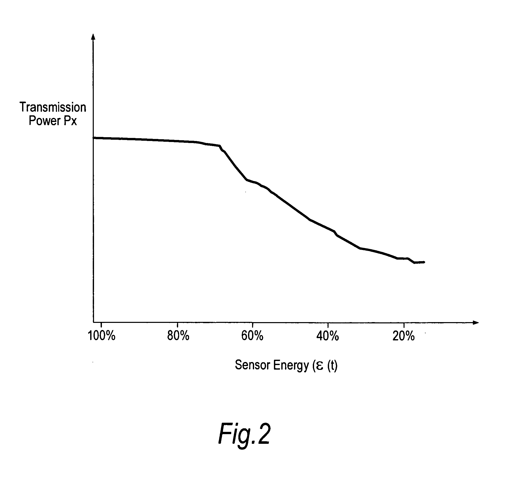
[0109]The second embodiment takes account of the needs of the sensors more completely by introducing the concept of a “desired rate” for transmission by each sensor. Each sensor's desired rate depends on its remaining energy (see FIG. 2 again), the amount of data the sensor needs to transmit, and its distance from the sink (candidate sink).

[0110]To reduce battery drain when a sensor is located close to the sink, the sensor might deliberately reduce the transmission rate depending on the remaining energy in its battery. Conversely the sensor should preferably increase the rate when the buffer occupancy is high, so as to ensure that gathered data is passed to the sink in a timely manner. To capture both concepts, a three-dimensional table is provided in each sensor which maps the current energy level, buffer occupancy and distance from the sink to a unique desired transmission rate R so that:

R=3D_Table(ε(t),d,data)  (11)

[0111]The second embodiment takes advantage of changes of the pro...


PUM


Abstract

In a wireless sensor network having a plurality of mobile sensor nodes (62, 63, 64, 65), a sink (70) is provided and re-positioned as required by assigning the role of sink to one of the mobile sensors at a time. Re-positioning involves finding candidate sinks in the vicinity of a current sink, a temporary sink or a central candidate in the network; judging the suitability of each candidate, for example by estimating the data throughput likely to be achieved if each candidate is selected as the new sink; and transferring the role of sink to the best candidate found. The temporary sink or central candidate may be selected with the aid of a positioning system (80) of the network. Suitability of a candidate sink may take into account a desired transmission rate of each sensor node in the vicinity of a candidate, this desired rate being found from a 3-D look-up table of each sensor.

Description

FIELD OF THE INVENTION[0001]The present invention relates to wireless sensor networks and more particularly to sink (base station) positioning in such networks.BACKGROUND OF THE INVENTION[0002]Recently, the concept of the wireless sensor network (WSN) has received considerable attention. A WSN typically includes a collection of low-power transceivers (henceforth called sensors) each having some kind of sensor function for one or more properties of an environment in which they are placed. The term “environment” here has a very broad meaning and could include, for example:—a geographical area such as a farmer's field, an area of ground requiring monitoring for security reasons, or a volcano; a specific facility such as an industrial plant, a hospital, a retail store or financial institution; or a human body. Likewise, the range of properties which might be sensed is wide, including temperature, pressure, sound, vibration, motion, the presence of specific chemicals, etc.[0003]Each sens...

Claims


Application Information

Patent Timeline
Patent Type & Authority Applications(United States)
IPC IPC(8): H04W4/00H04L12/28
CPCH04W40/04H04W84/18H04W40/32Y02D30/70
Inventor CHEBBO, HINDABEDI, SALED
Owner FUJITSU LTD
Why Eureka
Try Eureka