Method of removing diamond coating and method of manufacturing diamond-coated body

Inactive Publication Date: 2001-10-11
OSG
View PDF0 Cites 30 Cited by
  • Summary
  • Abstract
  • Description
  • Claims
  • Application Information

AI Technical Summary

Problems solved by technology

However, the diamond coating is hard to be ground due to a high degree of hardness thereof, and is accordingly difficult to be removed from the substrate.
Consequently, the rem

Method used


Image

  • Method of removing diamond coating and method of manufacturing diamond-coated body
  • Method of removing diamond coating and method of manufacturing diamond-coated body
  • Method of removing diamond coating and method of manufacturing diamond-coated body

Examples


Embodiment Construction

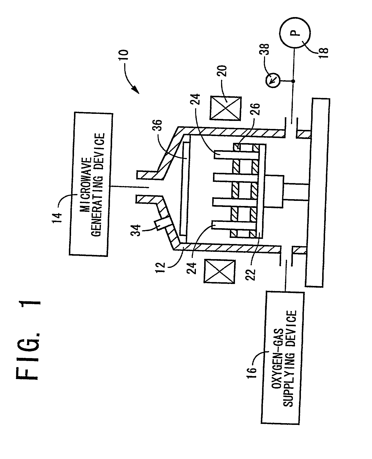
[0032] FIG. 1 is a view schematically shows a diamond-coating removing device 10 which is capable of burning a diamond coating of a diamond-coated tool and removing the diamond coating from the diamond-coated tool according to a method of the present invention. The diamond-coating removing device 10 may be a microwave plasma CVD device, so that the diamond-coating removing device 10 can be used for selectively burning and forming the diamond coating by changing the kind of gas supplied to the removing device 10. The diamond-coating removing device 10 includes a tubular furnace or reactor 12, a microwave generating device 14, a gaseous-oxygen supplying device 16, a vacuum pump 18 and an electromagnetic coil 20. The removing device 10 further includes a table 22 which is disposed in the tubular reactor 12, and a supporting member 26 which is disposed on the table 22. The supporting member 26 is designed to support a plurality of diamond-coated bodies in the form of diamond-coated tool...


PUM

PropertyMeasurementUnit
Pressureaaaaaaaaaa
Angleaaaaaaaaaa
Flow rateaaaaaaaaaa

Abstract

A method of removing a diamond coating from a substrate of a diamond-coated body which includes the substrate coated with the diamond coating. The method includes a step of heating the diamond-coated body at a predetermined temperature in a reactor at a predetermined reduced pressure, while introducing an oxygen gas into the reactor at a predetermined flow rate, for burning the diamond coating to thereby remove the diamond coating from the substrate.

Description

[0001] 1. Field of the Invention[0002] The present invention relates in general to a method of removing a diamond coating from a diamond-coated body, and a method of manufacturing a diamond-coated body by reutilizing a substrate from which the diamond coating has been removed.[0003] 2. Discussion of the Related Art[0004] There is known a diamond-coated body, such as a cutting tool (e.g., an end mill, a throwaway or disposable insert) and a semiconductor device (e.g., a semiconductor laser, a semiconductor sensor), having a surface which is coated with a diamond coating in the interest of increasing a degree of wear resistance and a degree of surface hardness of the body, as disclosed in JP-B2-59-27753 and JP-B2-2519037. As a method of coating a substrate with a diamond coating, there are proposed various methods such as a microwave plasma CVD (chemical vapor deposition) method, a high-frequency plasma CVD method and an ion beam method.[0005] Where the diamond coating of the diamond-...

Claims


Application Information

Patent Timeline
IPC IPC(8): B08B7/00B23B27/20B23P15/28C23C16/02C23C16/26C23C16/27C23C16/56C23G5/00
CPCB08B7/0071C23C16/0245C23C16/27C23C16/56C23G5/00
Inventor LIU, HAOHANYU, HIROYUKITANAKA, MASAHIRO
Owner OSG
Why Eureka
Try Eureka