Ratcheting pivot arm tensioner with backlash

a technology of pivot arm and tensioner, which is applied in the field of tensioners, can solve the problems of chain tension fluctuation, damage or rendering the engine inoperative, and chain tension fluctuation between excessively high or low levels

Inactive Publication Date: 2005-02-01
BORGWARNER INC
View PDF17 Cites 37 Cited by
  • Summary
  • Abstract
  • Description
  • Claims
  • Application Information

AI Technical Summary

Problems solved by technology

Prevention of such slippage is particularly important in the case of a chain driven camshaft in an internal combustion engine because jumping of teeth will throw off the camshaft timing, possibly causing damage or rendering the engine inoperative.
However, in the harsh environment of an internal combustion engine, various factors can cause fluctuations in the chain tension.
For instance, wide variations in temperature and thermal expansion coefficients among the variou

Method used


Image

  • Ratcheting pivot arm tensioner with backlash
  • Ratcheting pivot arm tensioner with backlash
  • Ratcheting pivot arm tensioner with backlash

Examples


Embodiment Construction

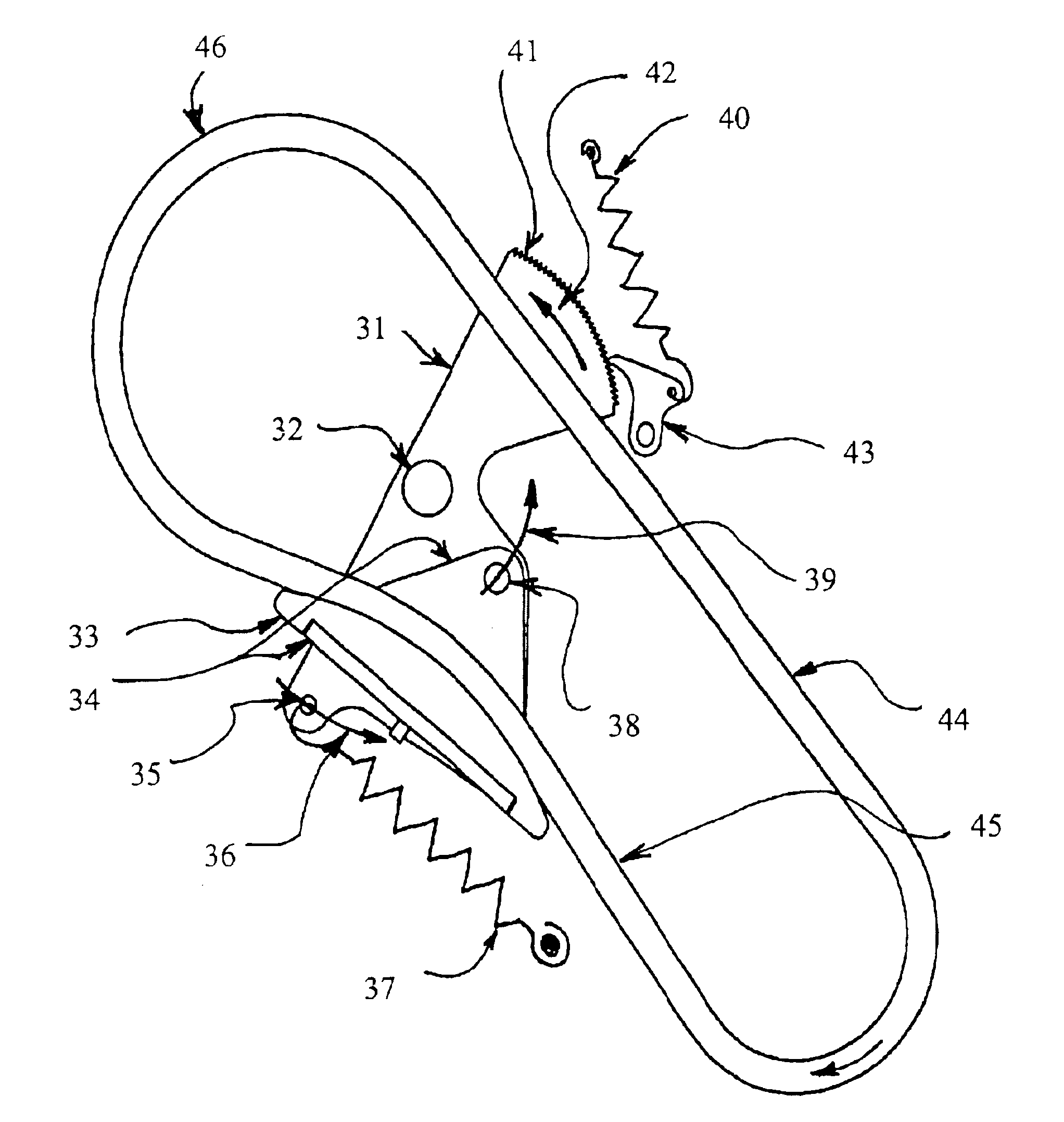
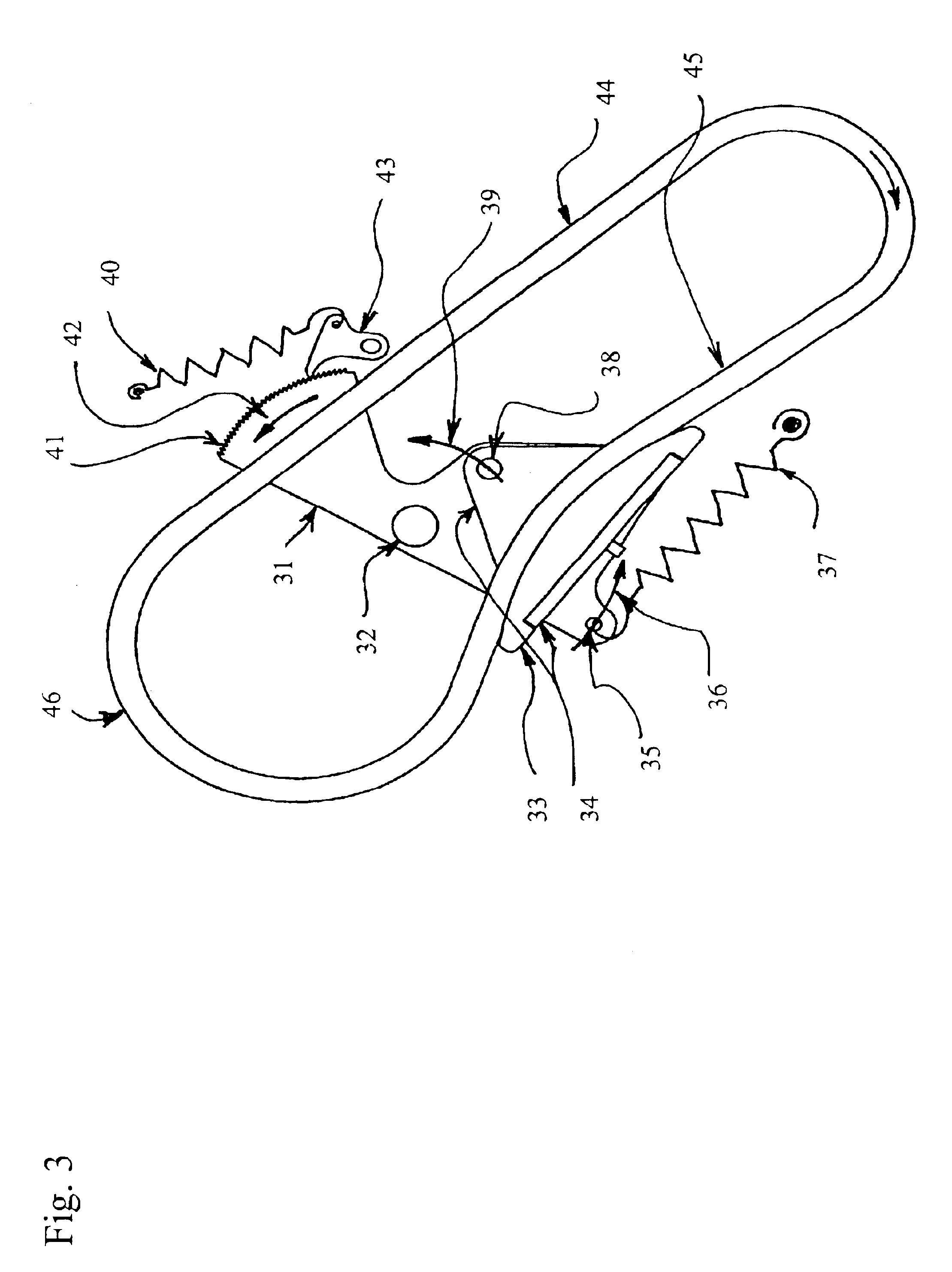
FIG. 3 shows a tensioner of the present invention. The tensioner is positioned to control a tight strand (44) and a slack strand (45) of a timing chain (46). FIG. 4 illustrates the tensioner of FIG. 3, rotated to illustrate the relationship in the z-direction. An arm (34) carries a shoe (33) positioned outside the slack strand (45) of the timing chain (46). The tensioner arm (34) takes up the slack and applies tension to the chain if moved in the direction of arrow (39). The arm (34) and shoe (33) are preferably attached by a fixed pin (38) to a tensioner pivot arm (31). The tensioner pivot arm (31) has a pivot feature at pivot (32). Tensioning occurs when a force is applied at point (35) in the direction of arrow (36). Rotational force in the direction of arrow (36) preferably results from an extension spring (37) attached at point (35). The type of biasing element used to apply this rotational force preferably includes, but is not limited to, a torsional spring, a compression spri...


PUM


Abstract

An engine chain or belt tensioning system includes a tensioner pivot arm with a ratcheting means that includes backlash in an engine timing system. The tensioner system includes a tensioner pivot arm having a fixed pin, ratchet teeth, and a connection for a rotation-causing device, all being spaced radially outward from a pivoting feature. The pivoting feature and the fixed pin are positioned between two strands of a chain. An arm carrying a shoe extended outside the strands of chain and positioned to contact an outside portion of chain is pivotally mounted to the fixed pin. Rotation of the pivot arm causes the arm and shoe to draw inwards, imparting tension to the chain strand. The ratchet teeth allow free rotation of the tensioner arm in one direction, but not the other.

Description

BACKGROUND OF THE INVENTION1. Field of the InventionThe present invention relates generally to tensioners used with chain drives in automotive timing and power transmission applications. In particular, the present invention is related to a ratcheting tensioner.2. Description of Related ArtA tensioning device, such as a hydraulic tensioner, is used as a control device for a power transmission chain, or similar power transmission devices, as the chain travels between a plurality of sprockets. In this device, the chain transmits power from a driving shaft to a driven shaft, so that part of the chain is slack and part of the chain is tight. Generally, it is important to impart and maintain a certain degree of tension in the chain to prevent noise, slippage, or the unmeshing of teeth in the case of a toothed chain. Prevention of such slippage is particularly important in the case of a chain driven camshaft in an internal combustion engine because jumping of teeth will throw off the camsh...

Claims


Application Information

Patent Timeline
IPC IPC(8): F16H7/08
CPCF16H7/0848F16H2007/0853F16H2007/0808
Inventor MARKLEY, GEORGE L.HUNGERFORD, JOSEPH W.
Owner BORGWARNER INC
Why Eureka
Try Eureka