Electrical connector

a technology of electrical connectors and clamps, which is applied in the direction of insulating bodies, basic electric elements, multi-purpose tools, etc., can solve the problems of unoptimized design, limited utility range, and unwieldy devices, and achieves the effect of convenient installation and simple structur

Inactive Publication Date: 2005-02-01
ARLINGTON INDS
View PDF8 Cites 143 Cited by
  • Summary
  • Abstract
  • Description
  • Claims
  • Application Information

AI Technical Summary

Benefits of technology

It is therefore an object of the present invention to provide a simpler and yet equally easily installed connector for the attachment of electrical cabling to electrical panel boxes, junction boxes and the like.
It is another object of the present invention to provide such a connector that is easily manufactured using conventional metal stamping techniques and therefore demonstrates a fabrication cost approaching that of molded or otherwise formed plastic, yet with the strength of steel.
It is yet a further object of the present invention to provide additional features such as the incorporation of an access port to permit easier extraction of armored cable secured in the snap-in connector of the present invention.

Problems solved by technology

Such devices are unwieldy and sometimes difficult to install, especially when space is limited, because of the number of parts involved and the need to apply screw drivers and wrenches to attain proper and secure attachment.
While both of the foregoing patented devices provide useful solutions to the stated problem of providing a simple to use cable connector, their design is not optimal since they rely largely on simple friction or the presence of a single sharp surface to inhibit “pullout” of the inserted cable.
Although the devices described in the foregoing patents allege an ability to retain a wide range of cable diameters, the range of their utility is really quite limited because of their design.
The manufacture of such a connector using conventional plastic molding techniques is, however, not simple and requires redesign of the connector to obtain the required serrated contact points in such a process.
While all such prior art connector devices provide useful solutions to the problem of connecting armored or other cable to electrical boxes of one type or another, they are either relatively costly, if made of cast metal, or may lack adequate strength if molded from plastic.

Method used


Image

  • Electrical connector
  • Electrical connector
  • Electrical connector

Examples


Embodiment Construction

This application relates to U.S. Pat. No. 6,604,400 filed concurrently herewith and entitled “Electrical Connector”, invented by the same inventor and relates to the continuity of application Ser. No. 09 / 603,756, now U.S. Pat. No. 6.335.88 which is a continuation of U.S. Pat. No. 6,080,933 which is a continuation of U.S. Pat. No. 6,043,432 all of which applications and patents ar incorporated herein by reference and made a part hereof.

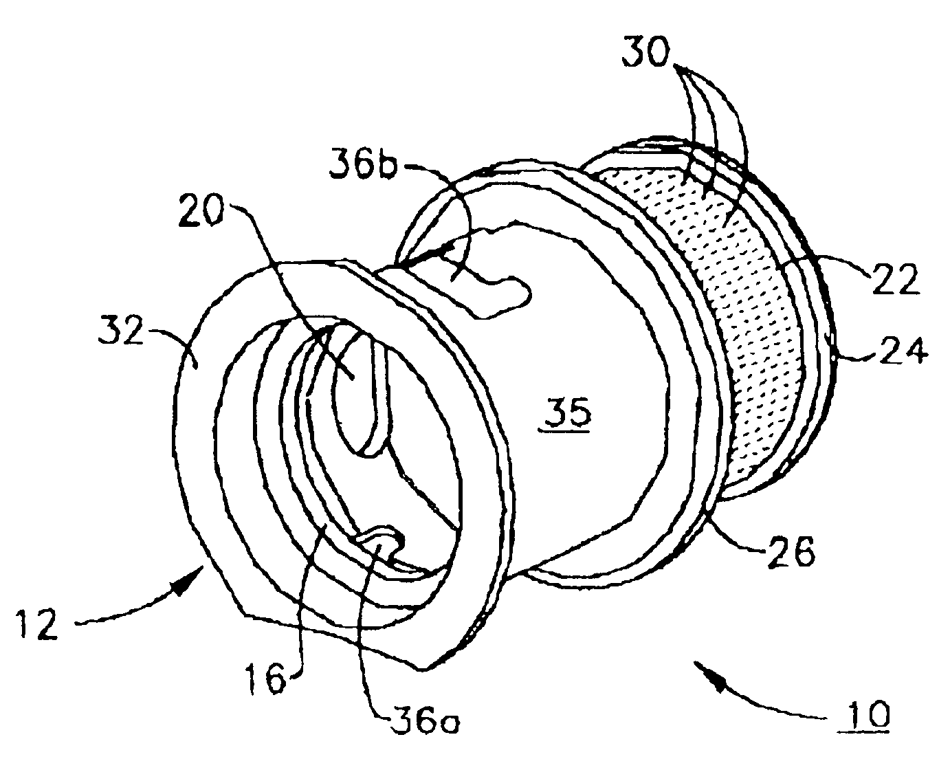
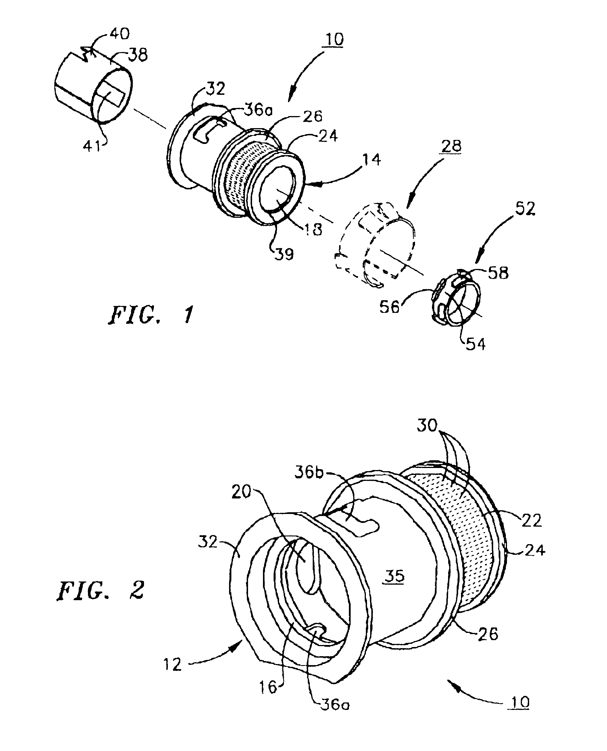
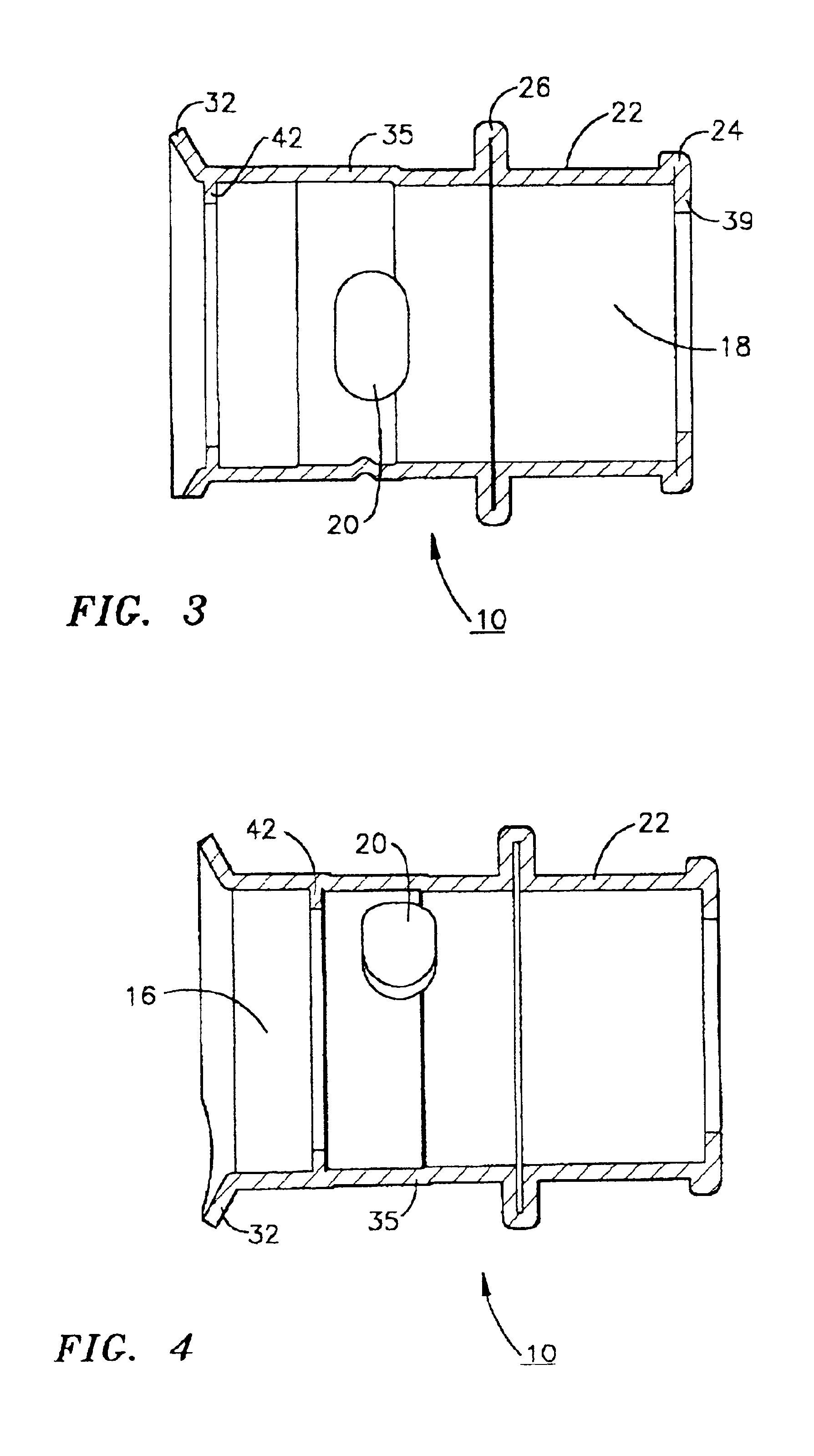
Referring now to FIGS. 1 and 2, the enhanced cylindrical housing 10 of the present invention is provided as a replacement for the die cast member identified as “18” in U.S. Pat. No. 6,080,933, which is hereby incorporated herein by reference in its entirety. Cylindrical housing 10 has an inbound or entry end 12 and an outbound or exit end 14 each including an aperture 16 and 18 respectively. Cylindrical housing 10 further includes an access port 20 whose multiple purposes will be described in greater detail hereinafter. Outbound end 14 further includes...


PUM


Abstract

According to the present invention there is provided a snap in locking cable connector with a cylindrical housing having an entry end aperture and an exit end aperture. The entry end aperture can accept the snap-in spring steel adapter of U.S. Pat. No. 6,080,933 as well as the exit end peripheral spring steel locking ring described in this patent to provide a connector that allows rapid and simplified installation of armored cable into a junction or circuit box. The cylindrical housing includes an annular groove or ridge about the inner periphery thereof in the area of the entry end for retention of the spring steel adapter. An electrical cable connector of this type that relies upon frictional or interference fit for retention of the spring steel adapter is also described. Retention of the spring steel adapter with a screw, rivet or similar fastener is also described.

Description

FIELD OF THE INVENTIONThe present invention relates to electrical cable clamps, and more specifically to electrical connectors including a back-out prevention feature for securing electrical cables to wiring enclosures.BACKGROUND OF THE INVENTIONThe wiring of electrical devices requires that electrical cables be inserted through openings or holes in junction boxes, panel boxes and the like. Electrical codes generally require that such access holes be substantially filled after insertion of electrical cable and the some means be provided to inhibit retraction of the electrical cable from the access hole after installation to eliminate the possibility of accidental disconnection of the electrical connections internal to the panel box, junction box, etc. The most commonly used connector to provide such utility until recently has been a two-part device that permitted passage of the cabling through a circular collar that passed through the access hole and provided means for securing the ...

Claims


Application Information

Patent Timeline
Patent Type & Authority Patents(United States)
IPC IPC(8): H02G3/02H02G3/08H02G3/06H02G3/18H02G3/22
CPCH02G3/0691H02G3/083H02G3/0616Y10T16/05H02G3/18H02G3/22
Inventor GRETZ, THOMAS J.
Owner ARLINGTON INDS
Why Eureka
Try Eureka