Electrical apparatus having resistance to atmospheric effects and method of manufacture therefor

a technology of atmospheric effects and electric devices, applied in the direction of electrical apparatus construction details, metallic pattern materials, printed electric components, etc., can solve the problems of significant electrical open circuits, and the likelihood of corrosion-caused shorting between termination structures, so as to reduce corrosion and reduce corrosion

Inactive Publication Date: 2005-02-01
TEXAS INSTR INC
View PDF10 Cites 4 Cited by
  • Summary
  • Abstract
  • Description
  • Claims
  • Application Information

AI Technical Summary

Benefits of technology

The technical effect of this patent is that it provides an easy way to make things less likely to rust or get damaged by water damage. This can be done with existing methods and materials already on hand, which saves money and time compared to buying new ones.

Problems solved by technology

The technical problem addressed in this patent relates to how to prevent corrosion from causing damage to electronic devices that are exposed to environments where there may be moisture or other harmful substances. Prior methods involving adding protective material require extra steps in the production process which can make things more complicated than necessary. The solution presented here involves integrating certain elements within the design of the electronics themselves, making them resistant to corrosion right from the start.

Method used


Image

  • Electrical apparatus having resistance to atmospheric effects and method of manufacture therefor
  • Electrical apparatus having resistance to atmospheric effects and method of manufacture therefor
  • Electrical apparatus having resistance to atmospheric effects and method of manufacture therefor

Examples


Embodiment Construction

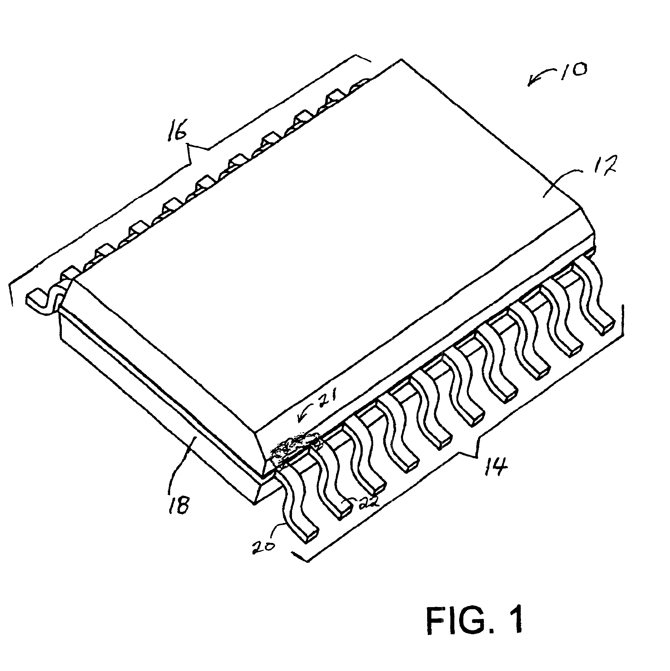
FIG. 1 is a perspective view of a first representative electrical apparatus with which the present invention may be employed. In FIG. 1, an electrical apparatus 10 includes at least one electrical device (not visible in FIG. 1) within a package structure 12. Access structures in the form of electrical terminations or leads 14, 16 effect electrical contact with electrical devices within apparatus 10. A substrate 18 may be included to cooperate with package structure 12 to substantially fully enclose electrical devices within apparatus 10 while accommodating electrical termination structures 14, 16 for effecting connection with the interior devices. Substrate 18 may also fixedly mount electrical devices within apparatus 10. Alternately, package structure 12 may substantially fully enclose electrical devices within apparatus 10 without a cooperating substrate.

The problem addressed by the present invention is illustrated in FIG. 1 as an area of corrosion 21. Corrosion 21 may bridgingly ...


PUM


Abstract

An electrical apparatus having resistance to atmospheric effects includes at least one electrical device and a packaging structure. The packaging structure substantially encloses the at least one electrical device. The packaging structure includes a corrosion-resisting agent.

Description


Claims


Application Information

Patent Timeline
Owner TEXAS INSTR INC
Why Eureka
Try Eureka