Microwave powered lamp with reliable detection of burned out light bulbs

a technology of light bulbs and micro-waves, which is applied in the direction of discharge tubes/lamp details, point-like light sources, light and heating equipment, etc., can solve the problems of high probability of permanent damage of magnetron b>12/b> by power being applied thereto, severe anode dissipation of magnets, and high power consumption

Inactive Publication Date: 2005-02-01
HERAEUS NOBLELIGHT AMERICA
View PDF14 Cites 10 Cited by
  • Summary
  • Abstract
  • Description
  • Claims
  • Application Information

AI Technical Summary

Benefits of technology

The present invention is a microwave powered lamp and method of control of a microwave powered lamp. The present invention replaces the prior art photocell and control circuit with a detector which is disposed within the housing of the microwave powered lamp which detects microwaves which are not coupled to the microwave excited lamp during operation of the magnetron and outputs a signal indicative of a level of received microwaves. A magnetron control is coupled to the detector which causes the magnetron to be turned off when a level of the detected signal indicates that the level of received microwaves exceeds a threshold. Since ignition of the microwave powered bulb represents an electrical load to the magnetron, the resultant level of microwave energy received by the detector, whether inside the microwave cavity / waveguide or inside the microwave housing, drops. The sensed microwave energy during normal bulb operation is below a level associated with non-ignition of the bulb such as that caused by bulb failure. A set period of time is allowed for the level of the detected microwaves to stabilize to avoid turning off of the magnetron power supply during transient voltage swings that occur during the first turning on of the bulb which otherwise might provide a false triggering signal turning off the magnetron power supply. With the invention, the sensing of the ignition condition (either on or off) of the bulb occurs reliably much more rapidly than with the prior art photocell and control circuit.
Additionally, the reliable detection of a non-ignition condition allows the power to be removed quickly from the magnetron long before any damage occurs from power not being absorbed by the plasma in bulb. This removes high stress and thermal loading of the magnetron as a result of the microwave output not being absorbed by the plasma in the bulb.

Problems solved by technology

The magnetron may also experience severe anode dissipation during the transient period.
Furthermore, the photocell 32 and control circuit 33 may fail requiring repair resulting in costly downtime for any system relying upon the operation of the microwave powered lamp and furthermore, if repair is not made, the probability of the magnetron 12 being permanently damaged by power being applied thereto is high.

Method used


Image

  • Microwave powered lamp with reliable detection of burned out light bulbs
  • Microwave powered lamp with reliable detection of burned out light bulbs
  • Microwave powered lamp with reliable detection of burned out light bulbs

Examples


Embodiment Construction

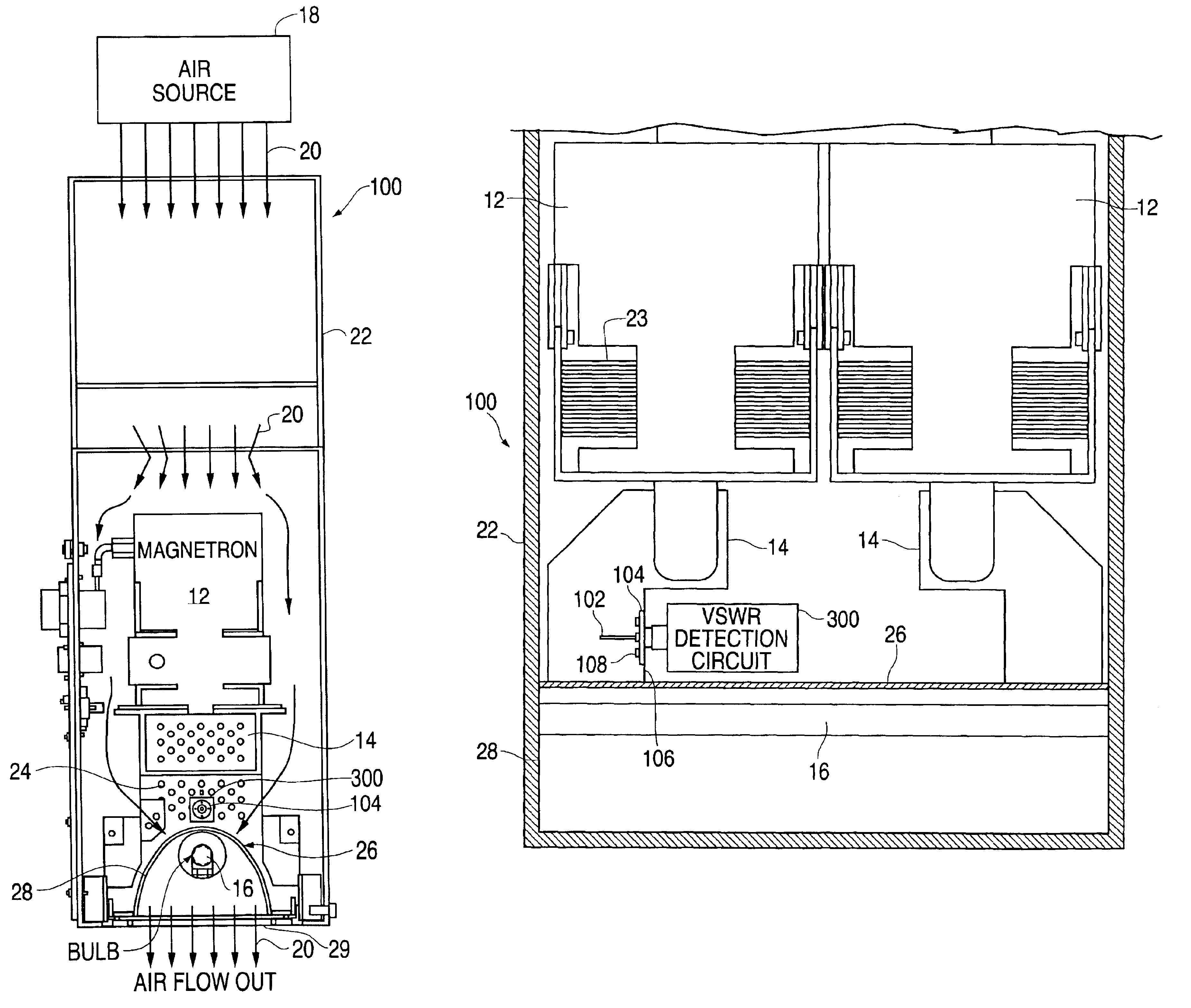
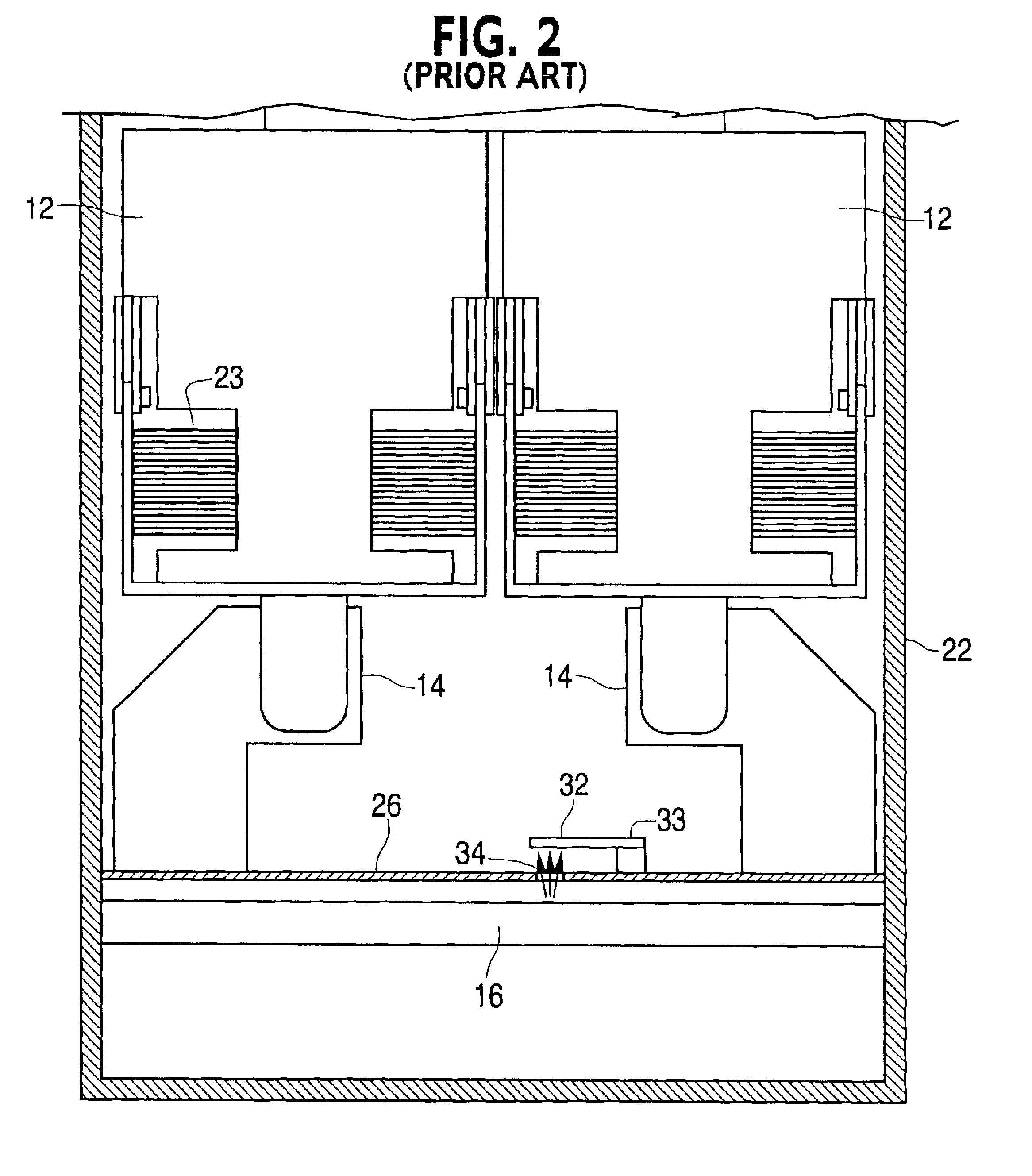
The present invention may be practiced in numerous microwave powered lamp designs with one acceptable design being the prior art microwave powered lamp design illustrated in FIGS. 1 and 2 as discussed in conjunction with first and second embodiments 100 and 200 respectively illustrated in FIGS. 3 and 4 and 5 and 6. With the invention the photocell 32 and control circuit 33 of the prior art are replaced with a microwave detector which is located within the microwave cavity / waveguide 14 or within the housing 22 of a microwave powered lamp 100 or 200 as respectively illustrated in FIGS. 3 and 4 and 5 and 6. The detector location in the housing may be with the detector extending into the microwave cavity / waveguide 14 where the VSWR is sensed, as illustrated in the embodiment 100 in FIGS. 3 and 4, or external to the microwave cavity / waveguide 14 but within the housing 22, as illustrated in FIGS. 5 and 6. In the first embodiment 100, as illustrated in FIGS. 3 and 4, a microwave probe 102 ...


PUM


Abstract

The invention is a microwave powered lamp (10). The lamp includes a light reflective cavity (28); an electrodeless bulb (16) contained in the light reflective cavity (26) from which light is emitted when the electrodeless bulb is excited by microwaves; a magnetron (12) for providing the microwaves for exciting the electrodeless bulb; a waveguide (14) which couples the microwaves emitted by the magnetron to the light reflective cavity for exciting the electrodeless bulb; a housing (22) which contains the lamp; a detector (102, 202) disposed within the housing, which detects the microwaves which are not coupled to the bulb during operation of the magnetron and outputs a signal indicative of a level of received microwaves; and a magnetron control (300), coupled to the detector, which causes the magnetron to be turned off when a level of the signal indicates the level of received microwaves exceeds a threshold.

Description

BACKGROUND OF THE INVENTION1. Field of the InventionThe present invention relates to microwave powered lamps and more specifically, to microwave powered lamps having reliable detection of bulb failure or degrading of performance.2. Description of the Prior ArtFIG. 1 illustrates a prior art microwave powered lamp 10 of the type sold by the Assignee of the present invention and as described in the Assignee's U.S. Pat. No. 6,445,138 which is incorporated herein by reference in its entirety. The microwave-powered lamp may be used to produce ultraviolet (UV) or visible light depending on the application such as, but not limited to, curing surface coatings. A magnetron 12 provides microwaves transmitted through a microwave cavity / waveguide 14 to a microwave excited bulb 16 which outputs light, as stated above, in either the UV or visible spectrum depending upon the application. An air source 18 blows air 20 through a housing 22 which contains the magnetron 12, microwave cavity / waveguide 1...

Claims


Application Information

Patent Timeline
Patent Type & Authority Patents(United States)
IPC IPC(8): H05B6/80H05B41/24F21S2/00F21Y101/00H01J65/04
CPCH05B41/24H01J65/044
Inventor BARRY, JONATHAN D.HELMS, KEITH A.
Owner HERAEUS NOBLELIGHT AMERICA
Why Eureka
Try Eureka