Sensor Device for Measuring the Rotational Speed at a Wheel of a Vehicle, Brake System and Vehicle Therewith and Measuring Method Which Can Be Carried Out Therewith for Measuring the Rotational Speed, and Braking Method

Active Publication Date: 2015-07-16
ZF CV SYST EURO BV
View PDF3 Cites 9 Cited by
  • Summary
  • Abstract
  • Description
  • Claims
  • Application Information

AI Technical Summary

Benefits of technology

[0004]Generally speaking, it is an object of the present invention to enable reliable measurement of wheel rotational speeds even in the case of a slo

Problems solved by technology

However, it is disadvantageous that an alternating voltage, which can be measured and evaluated, is induced in the passive sensor only when the pole wheel rotates relative to the rod sensor.
The amplitude of the alternating voltage is, moreover, dependent on the rotational speed of the pole wheel, with the result that low rotational speeds, which give rise to an amplitude that is insufficie

Method used


Image

  • Sensor Device for Measuring the Rotational Speed at a Wheel of a Vehicle, Brake System and Vehicle Therewith and Measuring Method Which Can Be Carried Out Therewith for Measuring the Rotational Speed, and Braking Method
  • Sensor Device for Measuring the Rotational Speed at a Wheel of a Vehicle, Brake System and Vehicle Therewith and Measuring Method Which Can Be Carried Out Therewith for Measuring the Rotational Speed, and Braking Method
  • Sensor Device for Measuring the Rotational Speed at a Wheel of a Vehicle, Brake System and Vehicle Therewith and Measuring Method Which Can Be Carried Out Therewith for Measuring the Rotational Speed, and Braking Method

Examples


Embodiment Construction

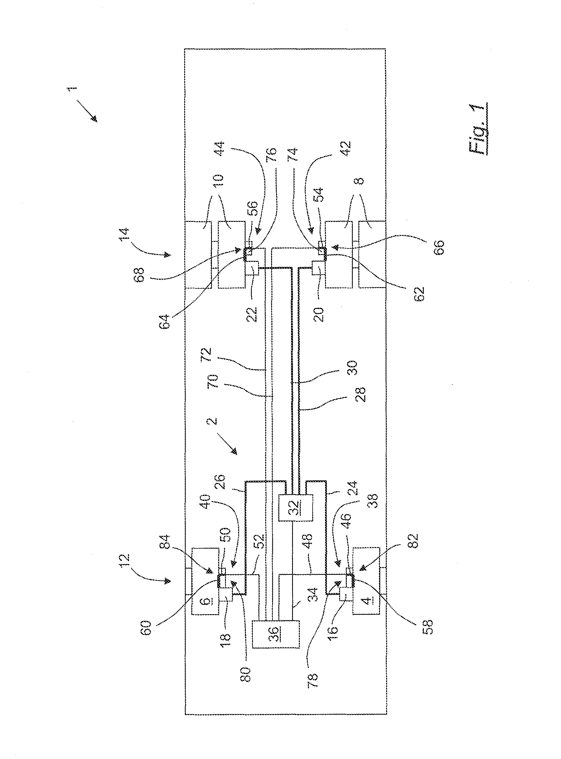
[0031]FIG. 1 shows a vehicle 1 according to an exemplary embodiment of the present invention. The vehicle 1 is embodied, by way of example, as a utility vehicle and as a road vehicle. In particular, the vehicle 1 is a motor vehicle that has its own drive (not illustrated) for example an internal combustion engine.

[0032]The vehicle 1 has a pneumatic brake system 2 for braking or arresting wheels 4, 6, 8 and 10 of the vehicle 1. It should be understood, however, that the present invention also has application with respect to hydraulic brake systems. The wheel 4 is a left-hand front wheel, the wheel 6 is a right-hand front wheel, the wheel 8 is a left-hand rear wheel, which is embodied as twin tires, and the wheel 10 is a right-hand rear wheel, which is embodied as twin tires. The front wheels 4 and 6 are arranged on a first axle 14, which is a front axle, and the rear wheels 8 and 10 on a second axle 14, which is a rear axle. In order to brake or arrest the wheels 4 to 10, a first bra...


PUM


Abstract

A sensor device for measuring the rotational speed at a wheel of a vehicle has a sensor carrier with an active sensor for actively sensing the rotation of a pole wheel rotating along with the wheel to measure rotational speed. The sensor carrier is constructed and arranged such that it can be clamped in the region of the wheel to permit the active sensor to be used without requiring complex adjustment operations.

Description

FIELD OF THE INVENTION[0001]The present invention generally relates to sensor devices for measuring rotational speed at vehicle wheels.BACKGROUND OF THE INVENTION[0002]EP 0 092 605 B2, for example, describes a rod sensor that has a passive sensor for passively measuring rotational speed by means of induction in brake systems of utility vehicles. During mounting, the rod of this known rod sensor is pushed into the securing opening or through the securing opening until it makes contact with the pole wheel, and is secured in the securing opening by means of a damping hushing, The measurement principle of the rod sensor by means of induction permits the sensor carrier to be attached in the securing opening in a positionally independent fashion in relation to rotations of the sensor carrier about the rod axis of the rod. This known rod sensor can therefore be installed without complex adjustment operations and therefore at low cost. However, it is disadvantageous that an alternating volt...

Claims


Application Information

Patent Timeline
IPC IPC(8): G01P3/49B60T8/171B60T8/32G01P1/02
CPCG01P3/49B60T8/329B60T8/171G01P1/026G01P1/00G01P3/487G01P3/488
Inventor DALISDAS, JURGENGRUNDKER, OLIVERHOFLER, SIEGFRIED
Owner ZF CV SYST EURO BV
Why Eureka
Try Eureka