

Liquid level sensing apparatus and method
a liquid level sensor and liquid level technology, applied in the field of techniques, can solve the problems of limiting the space for installation of liquid level meters and thermometers, difficult to take them out, and inability to adopt a typical differential pressure system as a liquid level meter
- Summary
- Abstract
- Description
- Claims
- Application Information
AI Technical Summary
Benefits of technology
Problems solved by technology
Method used
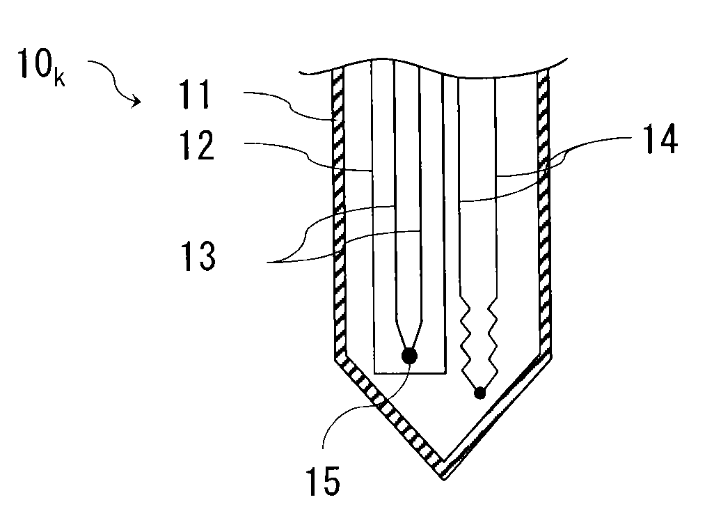
Image

Examples
first embodiment
[0021]Embodiments of the present invention will be described below with reference to the accompanying drawings.
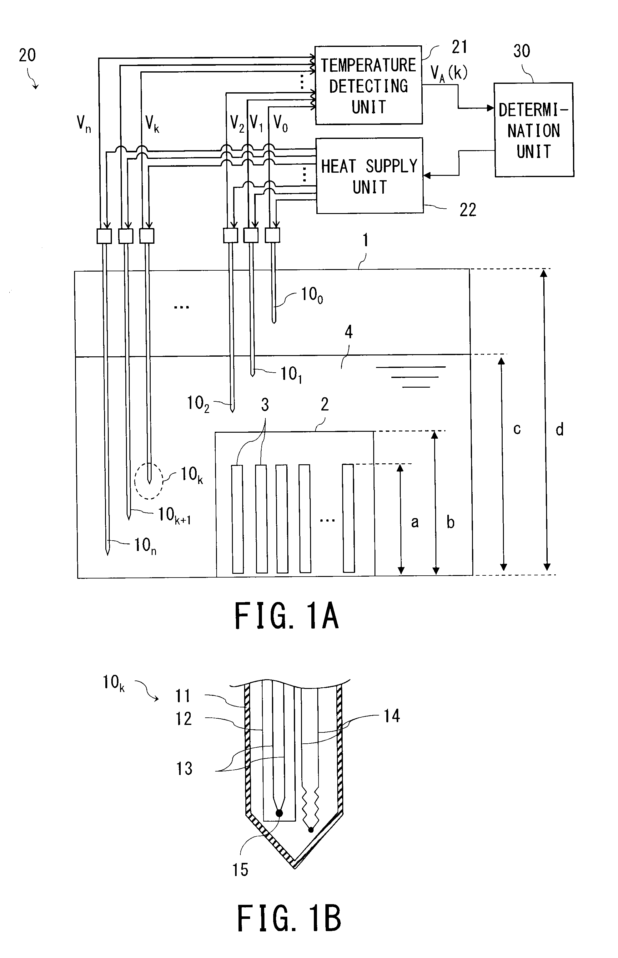
[0022]FIG. 1A shows a spent fuel storage pool 1 to which a liquid level sensing apparatus 20 according to the embodiments is applied.
[0023]A rack 2 adapted to store plural spent fuel assemblies 3 is placed in a spent fuel storage pool 1 (hereinafter also referred to as a “liquid holding vessel 1”). Furthermore, a circulation cooler (not shown) is placed in the spent fuel storage pool 1 to cool pool water 4 whose temperature is raised by decay heat of the spent fuel assemblies 3.
[0024]If, for example, length a of the spent fuel assemblies 3 is approximately 4.5 m (a=approximately 4.5 m) and height b of the rack 2 is approximately 5 m (b=approximately 5 m), a liquid holding vessel 1 with a depth of about 12 m is required (d=approximately 12 m) and a liquid level of the pool water 4 is kept at a normal water level c=approximately 11 m.
[0025]Consequently, a high-level of radiat...
second embodiment
[0058]Referring now to FIG. 5, a second embodiment of the present invention will be described.
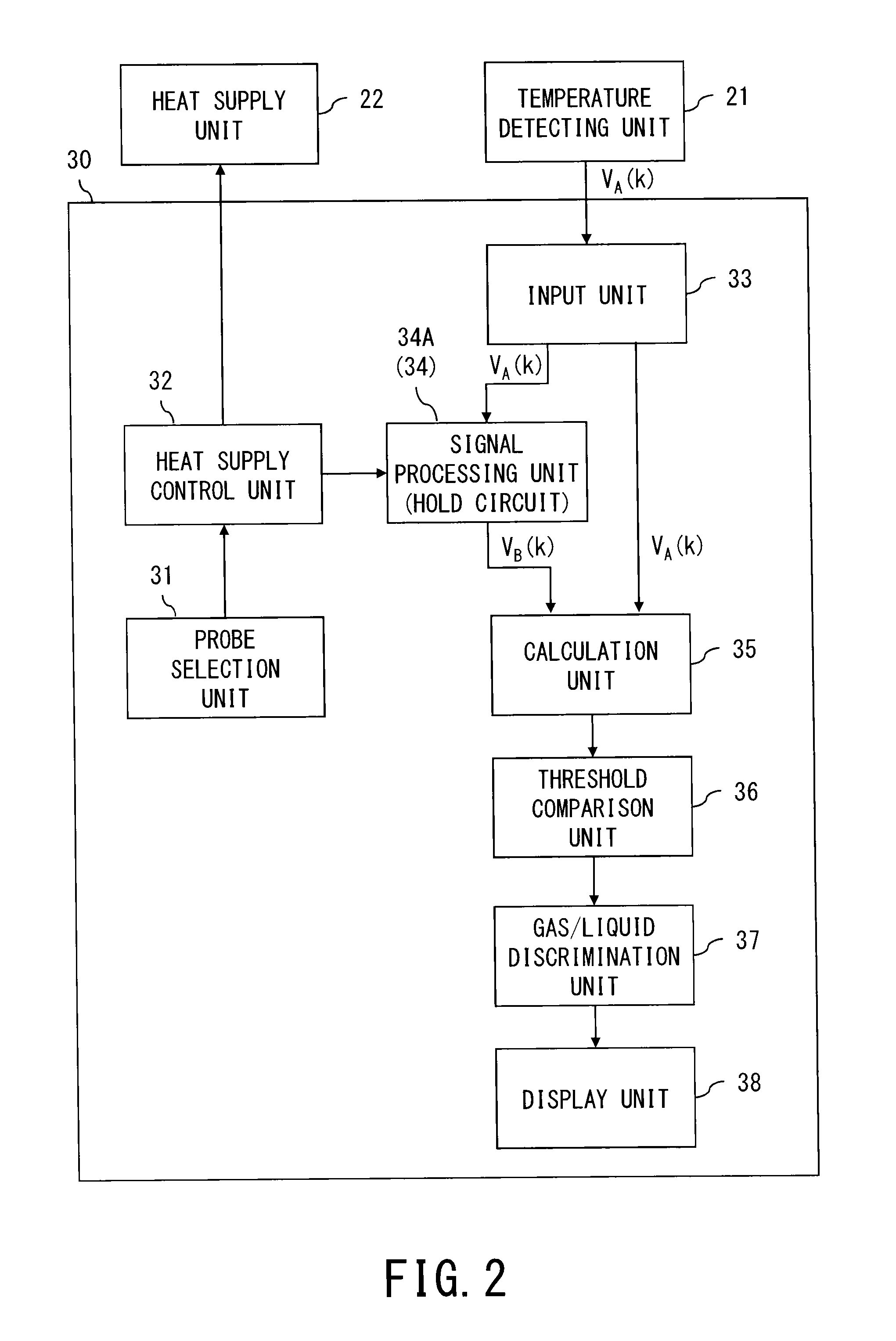
[0059]The second embodiment differs from the first embodiment in that a signal processing unit 34B (34) of the determination unit 30 is a first order delay circuit adapted to output a first order delay response to a temperature signal. In FIG. 5, components same as or equivalent to those in FIG. 2 are denoted by the same reference numerals as the corresponding components in FIG. 2, and redundant description thereof will be omitted.
[0060]In this way, since the signal processing unit 34B is configured as a first order delay circuit, a processing signal VB(k) for use in gas / liquid discrimination can be outputted to the calculation unit 35 in synchronization with heat supply without the need for a synchronizing signal from the heat supply control unit 32.
[0061]Also, such a first order delay circuit can be implemented solely by a resistor and capacitor, eliminating the need for the threshold com...
PUM
 Abstract
Description
Claims
Application Information