Abnormality detecting apparatus for mold clamping device

A technology for abnormality detection and clamping equipment, which is applied in the field of abnormality detection devices, and can solve the problems of inability to ensure proper movement of the crosshead and movable mold, increased cost of injection molding machines, and inability to detect the crosshead or movable mold.

Active Publication Date: 2007-06-06
FANUC LTD
View PDF7 Cites 9 Cited by
  • Summary
  • Abstract
  • Description
  • Claims
  • Application Information

AI Technical Summary

Problems solved by technology

[0007] However, in the methods described in JP7-16901A and JP2003-17478A, measuring devices such as pulse generators are provided on both the motor side and the driven side, and abnormalities in the belt transmission mechanism are detected, since it is necessary to provide measuring devices such as The pulse generator thus increases the cost of the injection molding machine
In addition, with the method described in JP2003-74649A, the abnormality of the belt is detected by whether or not the driven side pulley rotates, even if the driven side pulley rotates, the crosshead and the movable die cannot be guaranteed to move properly, therefore, sometimes the method is affected by the transmission mechanism Some abnormalities of the crosshead or the movement of the movable die cannot be detected
In addition, the methods described in JP2003-184967A and JP11-262932A require a tension detection device or a measuring device to detect the amount of rotation, which increases the cost of the injection molding machine
Moreover, in the method described in JP6-182845A, if the mold clamping device uses a crank lever mechanism, in the state where the crank lever mechanism is extended and generates a predetermined clamping force, the crank lever mechanism itself generates a clamping force to drive the crank lever The output torque of the motor of the mechanism crosshead decreases sharply, making it difficult to detect any abnormality in the belt transmission mechanism (such as breakage of the belt) from the motor output torque

Method used


Image

  • Abnormality detecting apparatus for mold clamping device
  • Abnormality detecting apparatus for mold clamping device
  • Abnormality detecting apparatus for mold clamping device

Examples


Embodiment Construction

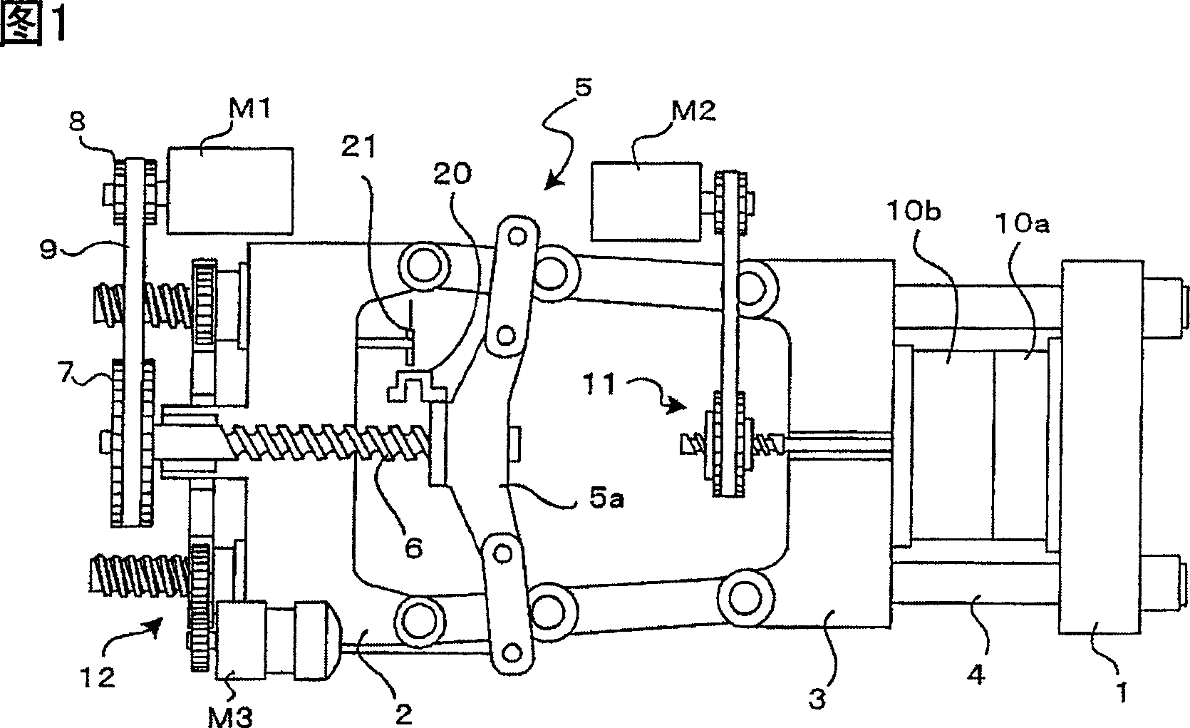
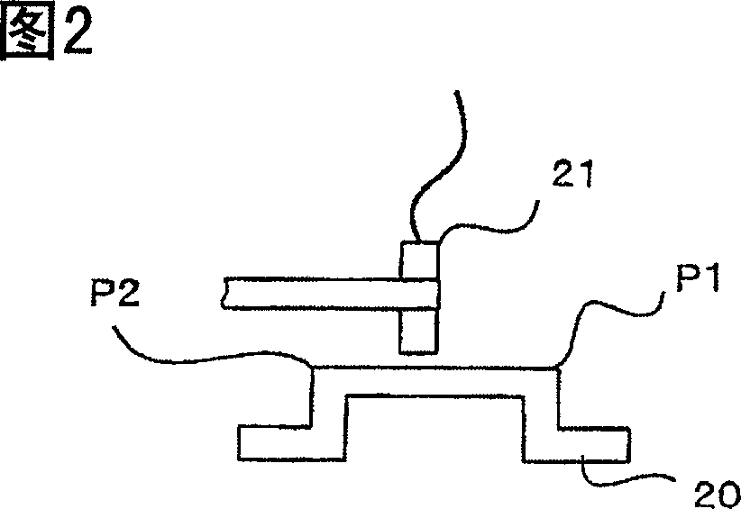
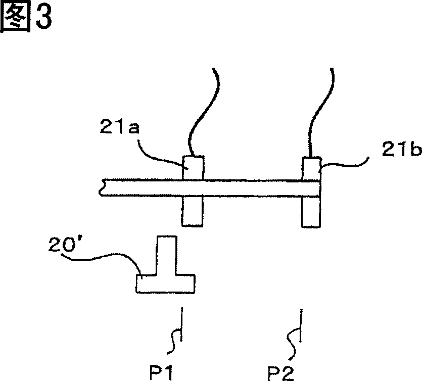
[0021] Fig. 1 is a schematic diagram showing one embodiment of a mold clamping device of an injection molding machine employing the mold clamping device abnormality detecting device of the present invention. The abnormality detecting device of the mold clamping device of the present invention is different from the prior art in that it includes a stopper 20 and a proximity switch 21 added to the abnormality detecting device of the conventional crank lever type mold clamping device.

[0022] The rear platen 2 is connected to a fixed platen 1 fixedly mounted on the base of the injection molding machine by a plurality of connecting rods 4 . The movable platen 3 is guided by the connecting rod 4 and can move freely. The crank lever mechanism 5 is located between the rear press plate 2 and the movable press plate 3, and the crosshead 5a of the crank lever mechanism 5 is installed on the ball nut engaged with the ball screw 6, so that the rotation of the ball screw 6 makes the ball n...


PUM


Abstract

An abnormality detection apparatus for a mold clamping device, having a simple configuration that can be constructed inexpensively. A dog is mounted on the crosshead of a toggle mechanism of the mold clamping device and a proximity switch is mounted on a rear platen. The shape of the dog and the location of the mounting of the proximity switch are adjusted so that the proximity switch switches ON at a mold touch position of mold touch and switches OFF when the toggle mechanism, which generates a predetermined clamping force, locks up. An alarm is output if the length of time during which the proximity switch is ON during the process of clamping the mold or opening the mold exceeds a predetermined reference value. If in the interval from mold touch to lock-up a large load is put on a servo motor and a belt that drive the crosshead and an abnormality such as breakage of the belt or the like occurs during this interval, it can be detected at once. Simply by adding a dog and a proximity switch enables breakage of the belt to be detected with ease.

Description

technical field [0001] The invention relates to an abnormality detection device of mold clamping equipment in an electric injection molding machine. Background technique [0002] In electric injection molding machines, the movable parts of the injection molding machine are driven by electric motors. Typically, the torque of the motor is transmitted to the movable parts of the injection molding machine through a belt transmission mechanism. Even in a mold clamping mechanism using a crank lever mechanism, the motor torque is converted from rotational motion of a ball screw / nut mechanism or similar mechanism to linear motion by a conversion mechanism that moves the crosshead of the crank lever mechanism to move the movable mold half movement to complete the closing, clamping and opening of the mold halves. [0003] When the crank lever type clamping mechanism is driven by a motor through a belt and ball screw / nut mechanism or similar mechanism, after the movable mold half con...

Claims


Application Information

Patent Timeline
Patent Type & Authority Applications(China)
IPC IPC(8): B29C45/84B29C45/76B29C45/66
CPCB29C45/84B29C2945/76943B29C2945/76394B29C45/661B29C2945/7623B29C45/768B29C2945/76869B29C2945/76076B29C2045/1792B29C2945/76391B29C2945/76086B29C2945/76872B29C2945/7609
Inventor 西村浩一桥本展明
Owner FANUC LTD
Why Eureka
Try Eureka