Navigation method and system for autonomous machines with markers defining the working area

a technology of autonomous machines and working areas, applied in the field of enclosed area navigation systems, can solve the problems of high cost of intermediate signs, inability to overcome, and robots perform very precise and delicate tasks, and achieve the effect of minimal time and high precision

Inactive Publication Date: 2005-02-01
F ROBOTICS ACQUISITIONS
View PDF79 Cites 111 Cited by
  • Summary
  • Abstract
  • Description
  • Claims
  • Application Information

AI Technical Summary

Benefits of technology

It has now been found, and this is an object of the present invention, that it is possible to free automated mechanisms operating within an enclosed zone from the need for preprogramming or predefined paths and rails, and from the need for intermediate navigation aids, and this to overcome the drawbacks of the prior art and to provide means by which a robot may perform its tasks within an enclosed area in a manner free from such limitations, with high precision and in a minimal period of time.
A further improvement in the precision of the determination of the actual coordinates of the robot on the map, at any given time, can be obtained by further providing on the boundaries a plurality of individually recognizable markers. Thus, when the robot reaches the boundaries, it not only identifies them by the proximity sensor, but may also receive the exact coordinates on the boundaries assigned to the specific marker it has detected. According to a preferred embodiment of the invention, when provided, the markers are substantially located at even distances from one another. Suitable markers will be easily recognized by the skilled person, and may comprise, e.g., an RF tag or magnetic tag.

Problems solved by technology

For instance, robots perform very precise and delicate tasks in the construction of electronic devices, or in medicine and aviation.
The major drawback of mobile robots, which the art has so far been unable to overcome, is the fact that their movements are limited to well predefined paths, normally requiring that they move along rails, or that they be provided with expensive navigation signs, positioned within the area in which they move, which operate as “stations” which redefine the exact position of the robot, and from which the program may direct the robot to the next station.
These intermediate signs are expensive, take up space, and are inconvenient to use, since they must be very precisely positioned and cannot be easily moved.
This approach entails severe drawbacks: first of all, when the robot moves within a predefined area by random walk, there is no way to ensure that the whole area will be covered by the tool which must operate thereon.
As a result, even though the robot may operate for a long period of time, unworked areas may be left at the end of the operation.
Secondly, if the area to be worked is irregular, or if it presents “islands ”, viz. areas which must not be worked, the random walk may lead to imperfect operation around such islands, as well as at those locations where the perimeter is of irregular shape.
Thirdly, because the operation of the robot is not programmed to obtain a predetermined coverage, it is necessary to allow the random walk to go on for a long period of time, so as to increase the chances of covering a major portion of the area to be worked.
This is not only energy consuming, but also leads to an increased wear of the equipment, and may also be environmentally undesirable due, e.g. to noise or other pollution caused by the operation of the robot.
Even if the robot is operated by sun energy, most of the aforesaid problems are not overcome, and additional problems exists, connected with such a mode of operation.
For instance, the robot may not work properly in areas of the world where sun radiation is scarce or low, and may be inoperative for substantial parts of the day, e.g., on cloudy weather.
This approach has two major drawbacks:a) it requires preprogramming by the user, which makes in unpractical for extensive consumer use; andb) it requires that such preprogramming is repeated each time something changes in the work area.

Method used


Image

  • Navigation method and system for autonomous machines with markers defining the working area
  • Navigation method and system for autonomous machines with markers defining the working area
  • Navigation method and system for autonomous machines with markers defining the working area

Examples


Embodiment Construction

The present invention will be better understood through the following illustrative and non-limitative description of preferred embodiments.

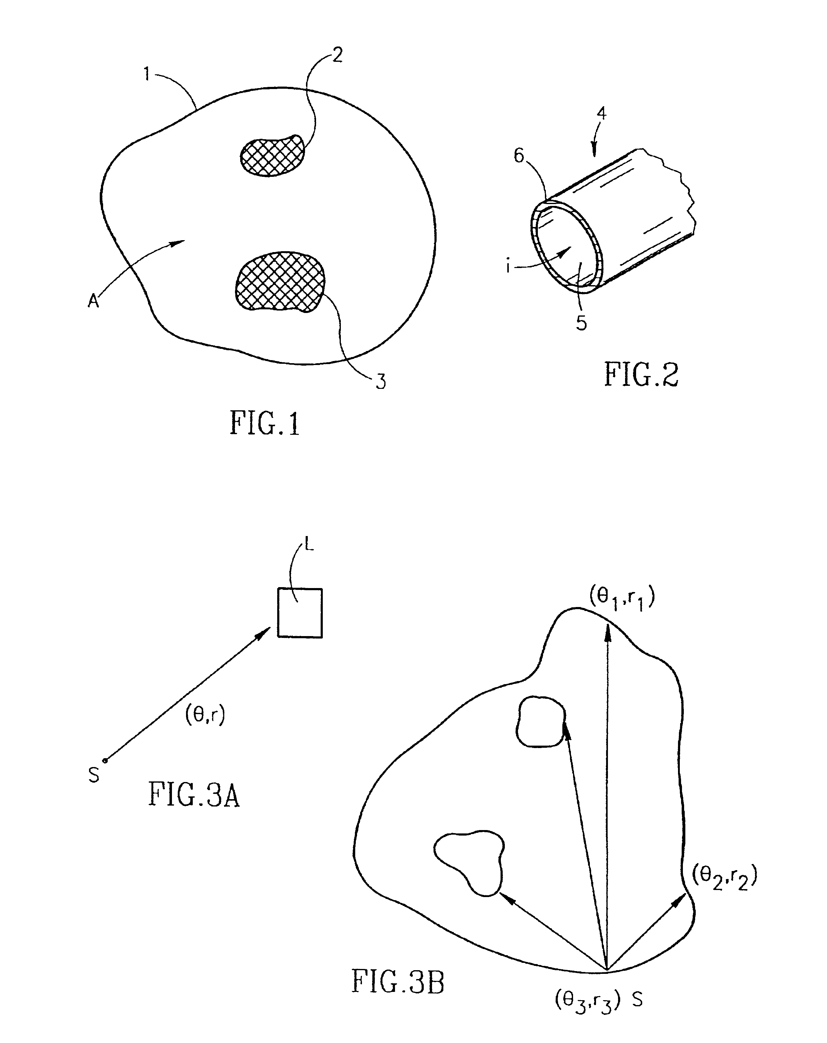
Looking now at FIG. 1, the working area in which the robot must operate, indicated at “A”, is enclosed by a boundary 1. Within the working area there are “islands” in which the robot must not penetrate, which are shadowed and enclosed by boundaries 2 and 3. According to one embodiment of the invention, the robot is an automated lawn mower, and the area A is a lawn. Islands 2 and 3 may be, e.g., trees and their vicinities or flower beds. Thus, we wish the mower to operate only in areas in which grass grows, and to avoid other areas. Alternatively, the robot can be coupled to a floor sweeper or a floor polisher or any other device which has to scan a flat surface.

As stated, according to one particular embodiment of the invention, the boundaries 1, 2 and 3 may comprise a conducting wire. This type of boundary is shown in cross-section in FIG. 2, whi...


PUM


Abstract

A method for automatically operating a robot, attached to a lawnmower or other unmanned machine, within an enclosed area is disclosed. The method includes the steps of: 1) providing the following elements: a proximity sensor positioned on the robot, a boundary along the perimeter of the working area and along the perimeter of each area enclosed in the working area in which the robot should not operate, the boundaries being detectable by the proximity sensor, a processing unit connected to the proximity sensor and receiving an input therefrom, a navigation unit on the robot to determine the coordinates of the robot relative to an arbitrary origin, a direction finder, and a memory to store values generated by the processing unit; and 2) causing the robot to move along each of the boundaries provided around or within the working area, to detect the boundaries and to memorize their shape, and to store in the memory values representative of the coordinates of the boundaries, thereby to generate a basic map of the working area. When the robot is to operate within the area, the method includes the steps of: (a) causing the robot to start from a starting point having known coordinates within the basic map of the working area; (b) continuously determining the coordinates of the robot by analyzing data obtained from the navigation unit and by detecting the vicinity of a boundary; and (c) correcting the actual position of the robot on the basic map by comparing the calculated and the actual coordinates of each detected boundary.

Description

FIELD OF THE INVENTIONThe present invention relates to a method and related systems for navigation in an enclosed area. More particularly, the invention relates to method and apparatus which can be used to cause an automated device to move and to perform predetermined tasks within an enclosed area.BACKGROUND OF THE INVENTIONThe use of automated devices is widespread nowadays, and finds countless applications. For instance, robots perform very precise and delicate tasks in the construction of electronic devices, or in medicine and aviation. Robots are also used in uses which require motion, notably, for automatic warehouses, where goods are retrieved and stored by means of computer-actuated robots. Other applications include, e.g., fetching raw materials in the course of industrial manufacturing, and removing and packaging finished pieces. In everyday's life, attempts have also been made to exploit robots for lawn mowing and for vacuum cleaning.The major drawback of mobile robots, wh...

Claims


Application Information

Patent Timeline
Patent Type & Authority Patents(United States)
IPC IPC(8): A01D34/00G05D1/02
CPCA01D34/008G01C22/00G05D1/0219G05D1/0227G05D1/0261G05D1/0263G05D1/0265G05D1/0274G05D1/0234A01D2101/00G05D2201/0216G05D2201/0208
Inventor PELESS, EHUDABRAMSON, SHAIDROR, GIDEON
Owner F ROBOTICS ACQUISITIONS
Why Eureka
Try Eureka