Control unit of a vehicle generator

a control unit and vehicle technology, applied in the direction of electric generator control, dynamo-electric converter control, transportation and packaging, etc., can solve the problems of shortening the lifetime of the vehicle system, auxiliary rectifier (excitation diode) b>2/b>, and requiring a large capacity, so as to achieve the effect of simple configuration

Inactive Publication Date: 2005-02-01
MITSUBISHI ELECTRIC CORP
View PDF22 Cites 12 Cited by
  • Summary
  • Abstract
  • Description
  • Claims
  • Application Information

AI Technical Summary

Benefits of technology

The present invention is intended to obviate the problems as referred to above, and has for its object to provide a control unit of a vehicle generator which is simple in config

Problems solved by technology

Thus, there arises a problem that the auxiliary rectifier (excitation diode) 2d is required to have a large capacity.
In addition, there is another problem that a large current flowing through the relay 6c generates

Method used


Image

  • Control unit of a vehicle generator
  • Control unit of a vehicle generator
  • Control unit of a vehicle generator

Examples


embodiment 1

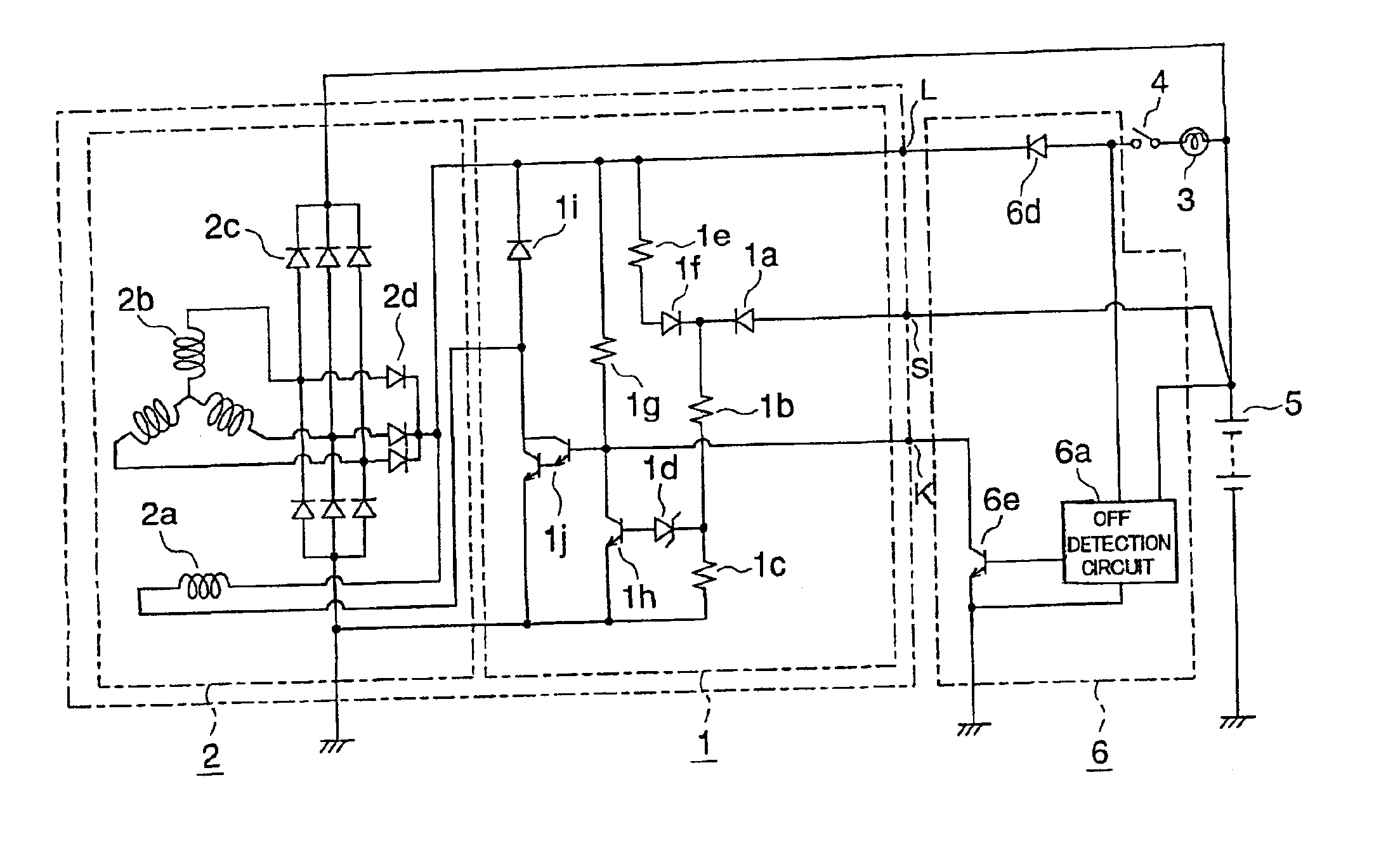
FIG. 1 is a circuit diagram in which the configuration of a control unit of a vehicle generator according to a first embodiment of the present invention is illustrated. In FIG. 1, the same or corresponding parts of this embodiment as those in the known control unit illustrated in FIG. 5 are identified by the same symbols, and a description thereof is omitted. The control unit according to the first embodiment illustrated in FIG. 1 is different from the above-mentioned known one illustrated in FIG. 5 in that there is added a power generation stop terminal K connected with the control terminal of the on-off control transistor 1j. In addition, the power generation stop circuit 6 is provided with a grounding transistor 6e which is made conductive based on an off detection signal of the off detection circuit 6a to ground the power generation stop terminal K. Here, note that the power generation stop circuit 6 is not provided with the transistor 6b and the relay 6c of the known control un...

embodiment 2

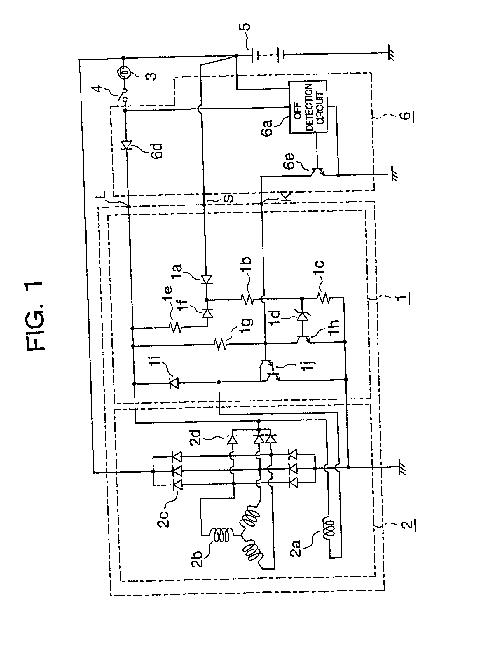
FIG. 2 is a circuit diagram in which the configuration of a control unit of a vehicle generator according to a second embodiment of the present invention is illustrated. In FIG. 2, the same or corresponding parts of the second embodiment as those of the known control unit illustrated in FIG. 5 are identified by the same symbols, and a description thereof is omitted. The second embodiment illustrated in FIG. 2 is different from the known control unit illustrated in FIG. 5 in that the power generation stop circuit 6 is provided with a transistor 6f, which is made conductive based on an off detection signal of the off detection circuit 6a indicative of the turning off of the key switch 4, and a transistor 6g, which has a resistor 6h connected between its base and collector, and is made nonconductive upon conduction of the transistor 6f. However, the power generation stop circuit 6 is not provided with the transistor 6b and the relay 6c of the known control unit.

In addition, the control...

embodiment 3

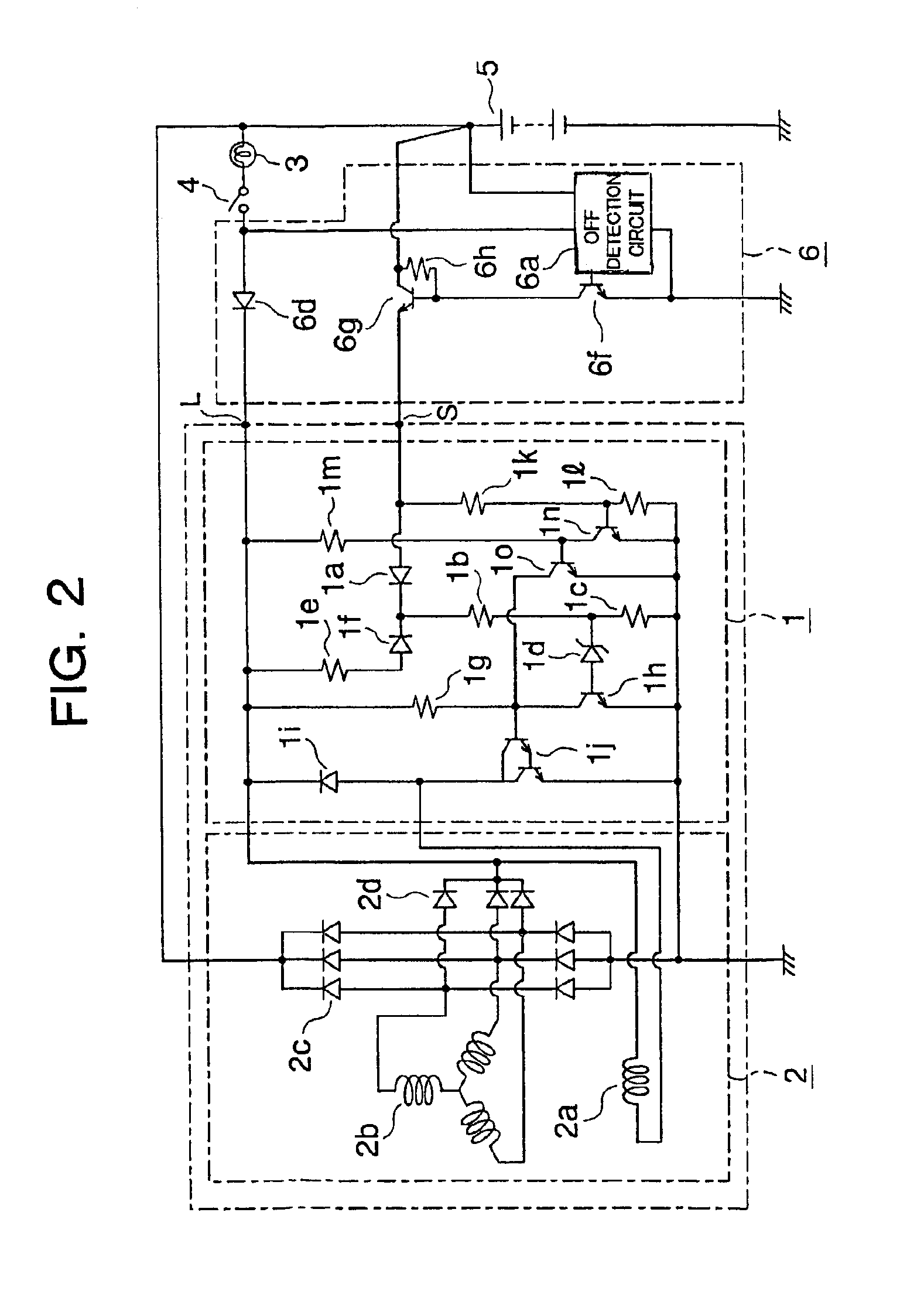
FIG. 3 is a circuit diagram in which the configuration of a control unit of a vehicle generator according to a third embodiment of the present invention is illustrated. In FIG. 3, the same or corresponding parts of this third embodiment as those of the second embodiment illustrated in FIG. 2 are identified by the same symbols, and a description thereof is omitted. The third embodiment illustrated in FIG. 3 includes a control circuit 1 of the same configuration as that of the second embodiment illustrated in FIG. 2 but is different therefrom in the configuration of a power generation stop circuit 6. The power generation stop circuit 6 of this third embodiment is provided with a resistor 6j and a transistor 6i which is made conductive based on an off detection signal of the off detection circuit 6a indicative of the turning off of the key switch 4, thereby grounding the voltage sensing terminal S. However, the power generation stop circuit 6 is not provided with the transistors 6f, 6g...


PUM


Abstract

A control unit of a vehicle generator is provided which is capable of instantaneously stopping power generation in a safe manner with an inexpensive system configuration without the need of interrupting a large current when a key switch is turned off. The control unit includes a vehicle generator (2), a battery (5) adapted to be charged by an output of the vehicle generator, and a control circuit (2) having an on-off control switching transistor (1j) for controlling the turning on and off of a field current of the vehicle generator. The control circuit is operable to interrupt the on-off control switching transistor (1j) when a detected voltage of the battery (5) is higher than a reference voltage, and make the on-off control switching transistor (1j) conductive thereby to control the voltage of power generation at a predetermined voltage when the detected voltage of the battery (5) is below the reference voltage. A power generation stop circuit (6) is provided which has an off detection circuit (6a) for detecting turning off of a key switch (4) of a vehicle. The power generation stop circuit (6) is operable to stop the power generation of the vehicle generator (2) when the off detection circuit (6a) detects the turning off of the vehicle key switch (4). A power generation stop terminal (K) is connected with a control terminal of the on-off control switching transistor (1j). The power generation stop circuit (6) controls the power generation stop terminal (K) to stop the power generation of the vehicle generator (2) instantaneously when the off detection circuit (6a) detects the turning off of the vehicle key switch (4).

Description

This application is based on Application No. 2001-175621, filed in Japan on Jun. 11, 2001, the contents of which are hereby incorporated by reference.BACKGROUND OF THE INVENTION1. Field of the InventionThe present invention relates to a control unit of a vehicle generator, and more particularly to such a control unit of a vehicle generator capable of instantaneously stopping power generation of the vehicle generator in a safe manner when a key switch 4 of a vehicle is turned off.2. Description of the Related ArtFIG. 5 is a circuit diagram illustrating the configuration of a known control unit of a vehicle generator which is capable of instantaneously stopping power generation of the vehicle generator upon turning off of a key switch 4 of a vehicle.In FIG. 5, the known control unit includes a control circuit 1 for controlling the generation voltage of a vehicle generator 2, which is driven by an engine (not shown), at a predetermined voltage, a charge lamp 3, a key switch 4 of a vehi...

Claims


Application Information

Patent Timeline
IPC IPC(8): H02J7/16H02J7/14H02J7/24H02P9/10H02P9/04H02P9/14
CPCH02J7/1446H02P9/10H02J7/244Y02T10/92H02J7/243
Inventor KOUWA, TATSUKI
Owner MITSUBISHI ELECTRIC CORP
Why Eureka
Try Eureka