
Swapped pixel pages

a pixel page and pixel technology, applied in the field of video data storage, can solve the problems of sdram being typically more expensive than sdram, incurred additional delay, and loss of speed

Inactive Publication Date: 2005-02-01
SONY CORP +1
View PDF52 Cites 13 Cited by
  • Summary
  • Abstract
  • Description
  • Claims
  • Application Information

AI Technical Summary

Problems solved by technology

To change pages, a new page address is used and an additional delay is incurred from both the extra address cycle and a delay in the memory changing which page is active.
This delay is referred to as a “page miss” and can result in a loss in speed.
SRAM (static random access memory) typically does not incur the same page miss delay as SDRAM, but SRAM is typically more expensive than SDRAM.
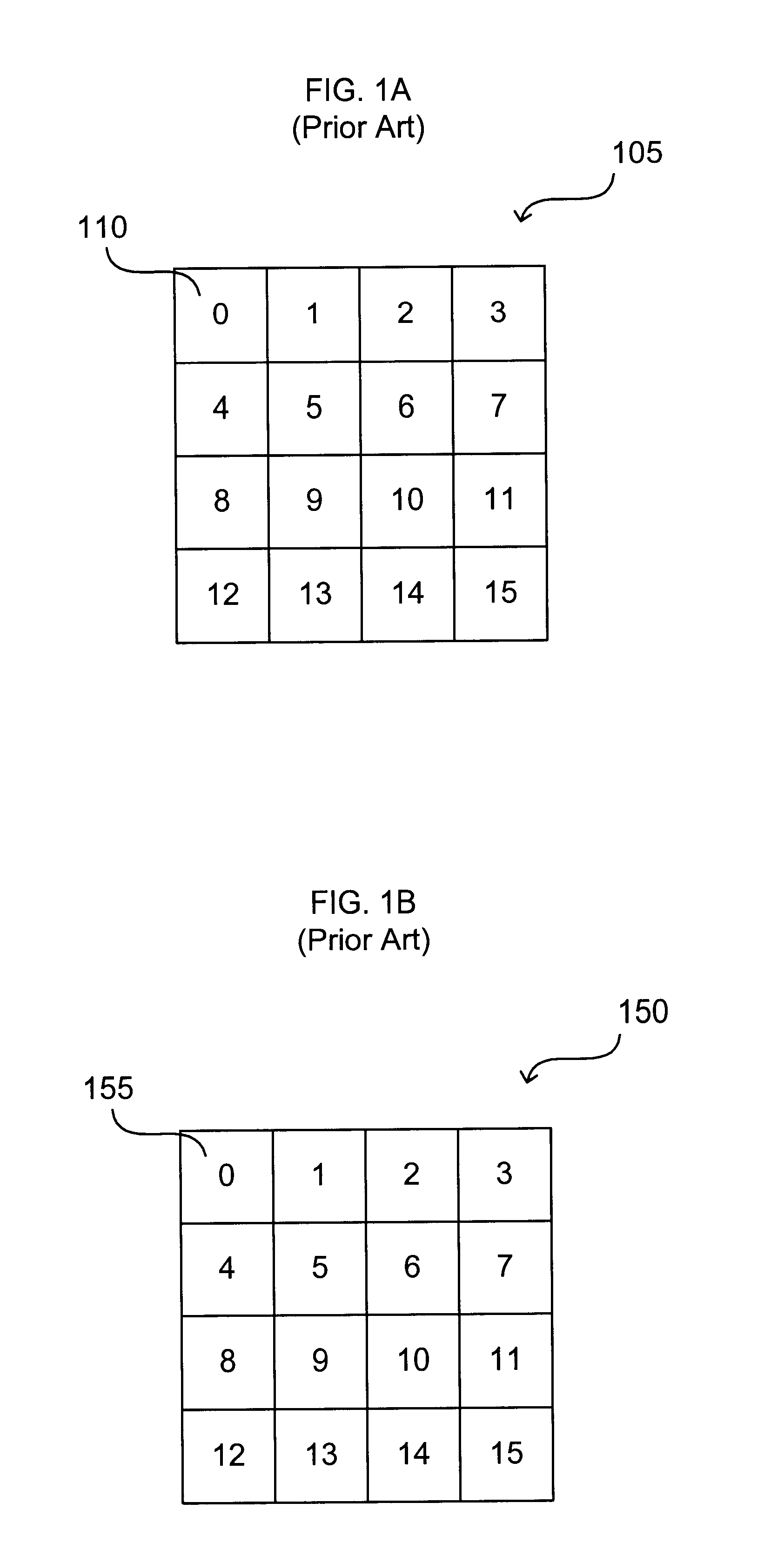
The pixel data for pixels in different rows are typically not stored in the same page, and so page misses occur when pixel data is to be stored or retrieved for pixels from different rows.

Method used


Image

  • Swapped pixel pages
  • Swapped pixel pages
  • Swapped pixel pages

Examples


Embodiment Construction

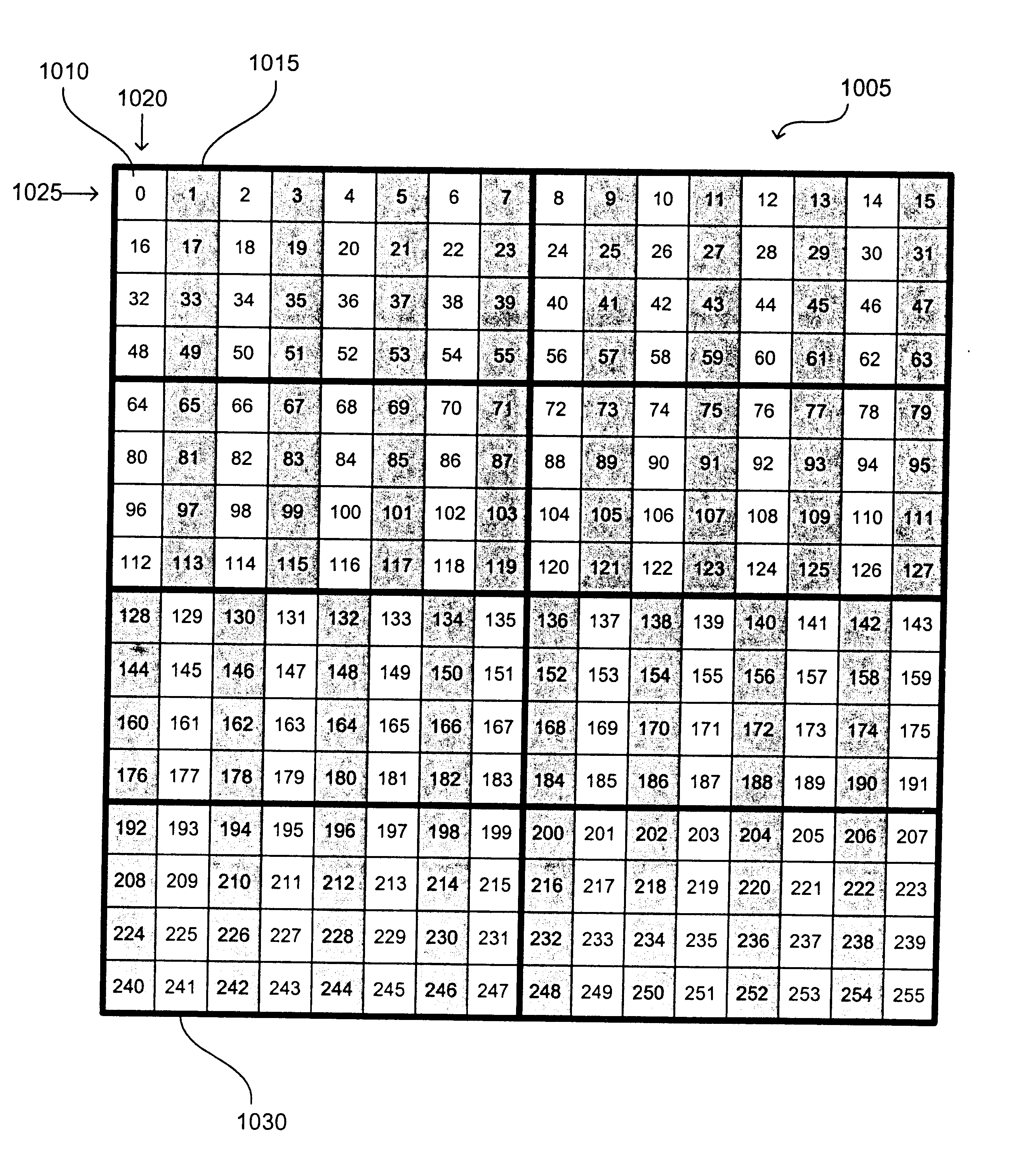
The present invention provides methods and apparatus for implementing a pixel page system providing swapped pixel pages for use with a GLV (grating light valve). As described above, a GLV projects an image using a horizontal scan (one column of pixels at a time, sweeping from left to right). Accordingly, it is advantageous to provide pixel data to a GLV according to vertical columns of pixels in a frame. One implementation of a GLV receives pixel data in two streams: one for the upper half of a frame of pixels and one for the lower half of the frame. Swapped pixel pages provide parallel retrieval of pixel data from the upper and lower halves of a frame of pixel. Accordingly, swapped pixel pages can be used to provide two parallel pixel data streams to a GLV.

As described in the related U.S. application Ser. No. 10 / 051,538, filed Jan. 16, 2002, a pixel page is a two-dimensional array of pixels. A pixel page maps pixel data to memory locations for a region of pixels from multiple rows ...


PUM


Abstract

Methods and apparatus for implementing a pixel page system providing swapped pixel pages for use with a GLV (grating light valve). In one implementation, a swapped pixel page system includes: a data source, providing pixel data for pixels in a first order, where each pixel is in a frame of pixels, the frame having horizontal rows of pixels, vertical columns of pixels, an upper half, and a lower half; a data destination, receiving pixel data for pixels in a second order; and at least two memory devices, each memory device having a plurality of memory pages including a plurality of memory locations, each memory location having an address; where pixel data for each pixel corresponds to an entry in one of a plurality of swapped pixel pages, each swapped pixel page having a plurality of pixel page rows each including a plurality of pixels and a plurality of pixel page columns each including a plurality of pixels, where pixel data is stored to the memory devices in the first order and retrieved from the memory devices in the second order, and where each memory page stores pixel data in multiple locations according to the first order and stores pixel data in multiple locations according to the second order, and where pixel data is retrieved in parallel for two pixels from different halves of the frame of pixels.

Description

BACKGROUNDThe present invention is related to video data storage. More particularly, the present invention is related to video display systems and frame buffers. Several related technologies are discussed below (in labeled sections for clarity).1. Raster Scan DisplaysA common type of graphics monitor is a conventional raster-scan display using a cathode ray tube (“CRT”). As is well known, in a typical CRT, an electron beam strikes phosphor on the inner surface of the screen producing light visible on the outer surface of the screen. By controlling the electron beam different locations of the screen can be struck, creating a pattern and hence a video image. In a typical CRT raster-scan display, the screen area is divided into a grid of pixels (or picture elements). The electron beam sweeps from left to right across the screen, one row at a time from top to bottom, progressively drawing each pixel on the screen. Each row of pixels is commonly referred to as a scan line. In this type o...

Claims


Application Information

Patent Timeline
Patent Type & Authority Patents(United States)
IPC IPC(8): G06T1/60G09G5/395G09G5/391G09G5/399G09G5/39G09G5/393G09G5/36G11C7/10H04N7/01H04N5/14G09G3/34G09G3/00H04N5/46H04N5/74H04N5/44
CPCG06T1/60G09G5/39G11C7/1042H04N5/14H04N7/01H04N7/0132G09G3/34G09G5/393G09G5/399G09G2340/0407G09G2352/00G09G2360/12G09G2360/122G09G2360/123G09G2360/128H04N5/46H04N5/7416H04N7/012G09G3/001
Inventor CHAMPION, MARK
Owner SONY CORP
Learn More