
Direct conversion receiver

a receiver and receiver technology, applied in the direction of radio transmission, electrical equipment, transmission, etc., can solve the problem of adding significantly to the cost of small portable radio devices such as receivers and transceivers

Active Publication Date: 2005-02-01
SIGE SEMICON
View PDF1 Cites 88 Cited by
  • Summary
  • Abstract
  • Description
  • Claims
  • Application Information

AI Technical Summary

Benefits of technology

In accordance another aspect of the invention, a method of operating a radio transceiver to alternately receive and broadcast radio frequency signals comprises the steps of:a) generating a local signal of a frequency similar to a radio frequency signal intended for reception and for broadcast;b) mixing received signals with the local signal to generate mixed signals including a difference signal;c) deriving a baseband signal by suppressing any mixed signals being of frequencies greater than a maximum bandwidth of frequency modulation information intended for reception;d) continuously generating an alternating current signal;e) adjusting a frequency of the alternating current

Problems solved by technology

The demand for wireless communications can be said to be inversely related to the cost of providing portable radio transceivers.
Provision of such in discrete form with the required interconnections adds significantly to the expense of manufacture of small portable radio devices such as receivers and transceivers.

Method used


Image

  • Direct conversion receiver
  • Direct conversion receiver

Examples


Embodiment Construction

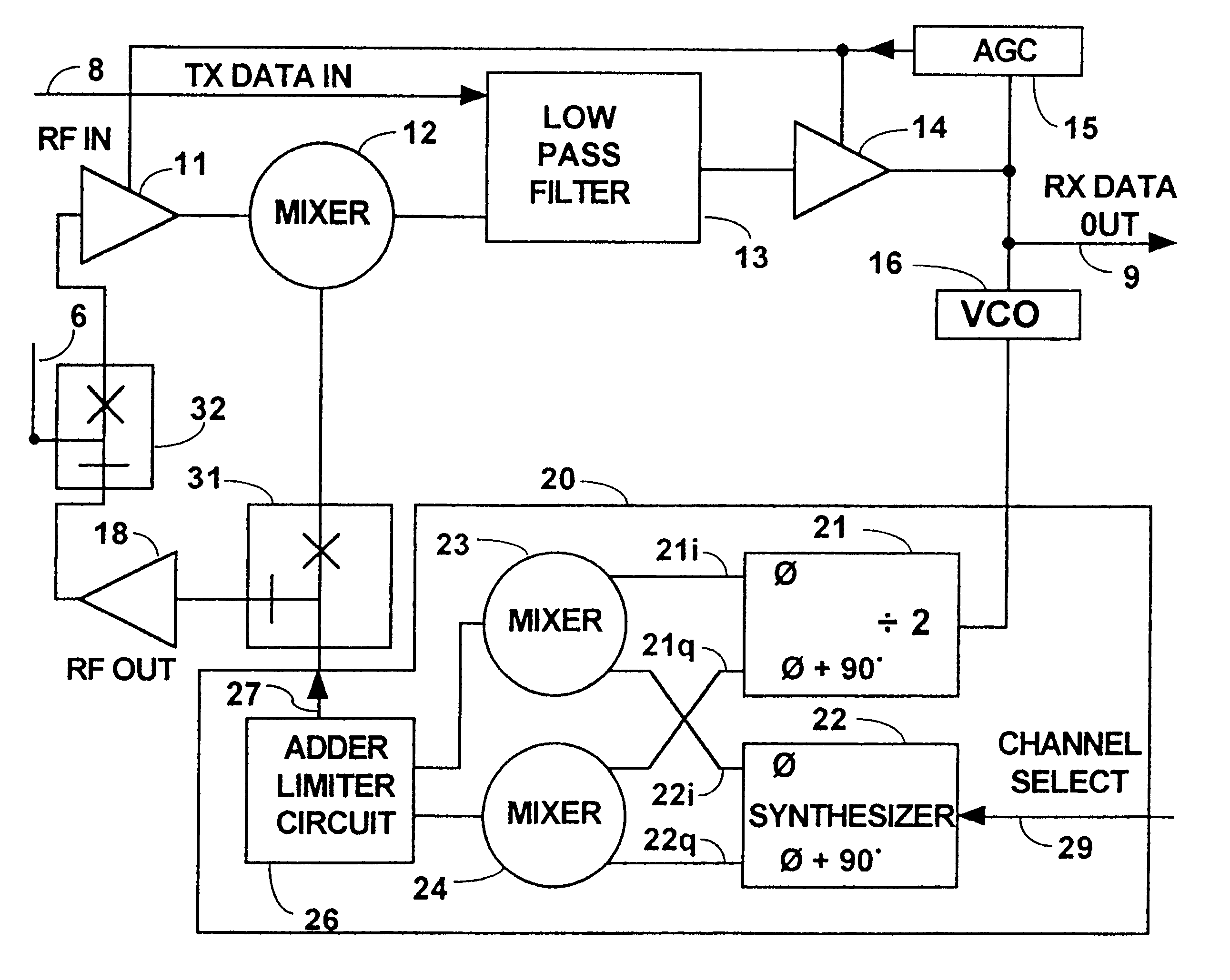
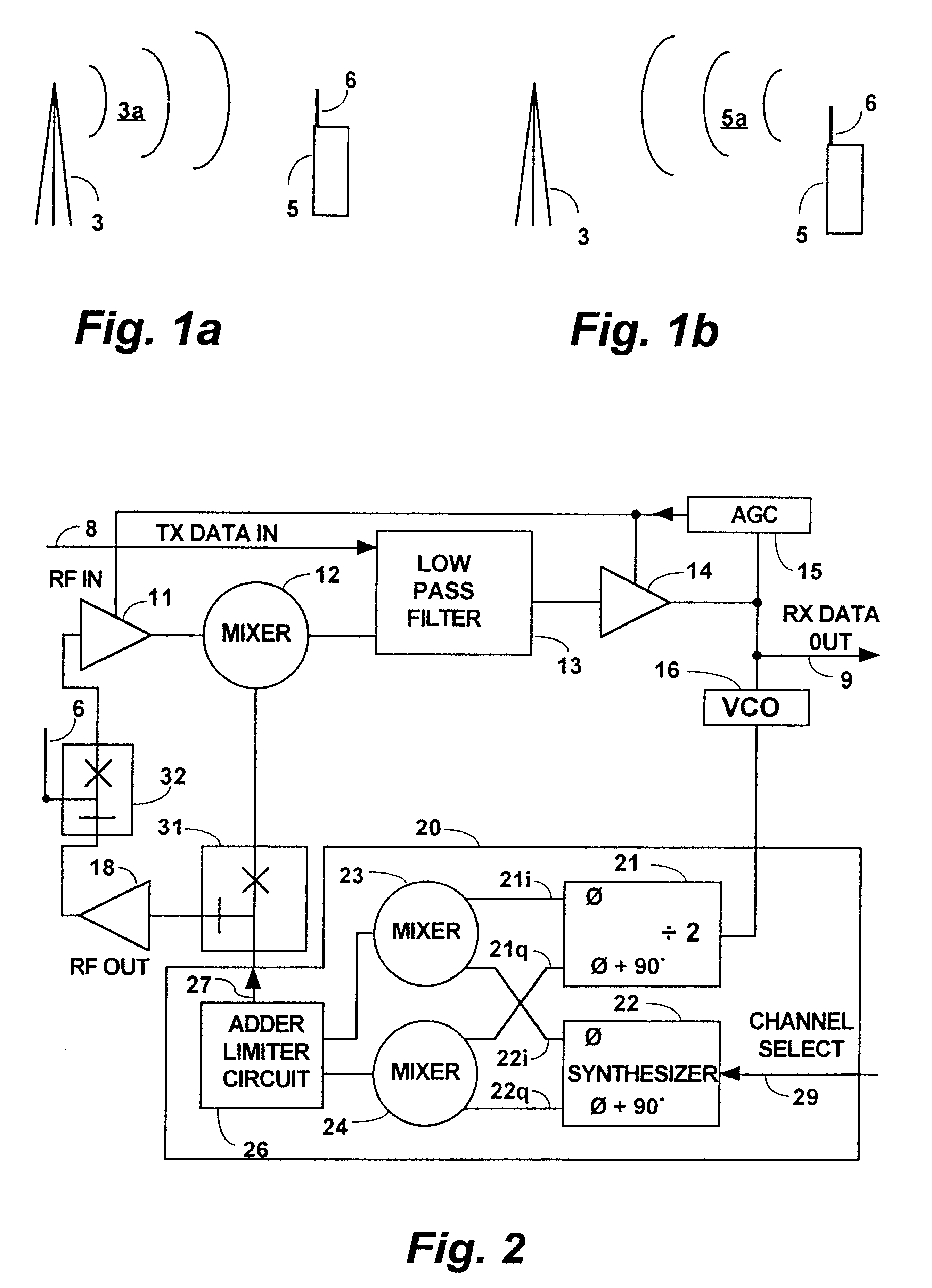
In FIGS. 1a and 1b a tower mounted or otherwise elevated radio antenna 3 provides a link between a portable communications device 5 and a communications network, not shown. The communications network may be linked by radio signals with the portable communications device 5 in accordance with any of several known methods including simplex, wherein the portable communications device 5 responds to a signal broadcast from the antenna 3 by broadcasting a signal itself. For example in FIG. 1a the antenna 3 broadcasts a radio signal burst 3a at a frequency intended for reception by an antenna 6 of the portable communications device 5. Subsequently, after the portable communications device 5 has received the radio signal burst 3a, it responds by broadcasting a radio signal burst 5a of a similar, preferably identical frequency, via the antenna 6. When the portable communications device 5 is in active use for communication with another device via the network, these depicted functions occur rep...


PUM


Abstract

In a frequency modulation radio receiver with direct conversion, a local oscillator signal is generated having a frequency within a preselected frequency range and the frequency is varied in response to a variable low frequency signal; the local oscillator signal is mixed with a received signal to provide a baseband signal. The variable low frequency signal is generated by a controlled oscillator in inverse relationship to a direct current component in said baseband signal. In a frequency modulation radio transceiver a broadcast function is provided by varying the low frequency signal with an information signal with the resulting local oscillator frequency being varied accordingly and amplified for broadcast. The transceiver is controlled to operate alternately in either a receive mode and a broadcast mode at substantially the same frequency. While in the receive mode the controlled oscillator causes the local oscillator signal to be drawn toward the carrier frequency of a received signal yielding preferred direct conversion of modulating information into the base band.

Description

The invention is in the field of radio transmitters and radio receivers and more particularly relates to radio transceivers wherein some of the components are used in common for both the reception and the transmission of frequency modulated radio signals.BACKGROUND OF THE INVENTIONThe demand for wireless communications can be said to be inversely related to the cost of providing portable radio transceivers. Hence it is preferred that such transceivers be provided substantially in an integrated circuit form to minimize cost.A radio transceiver has two functions, one being that of broadcasting an information signal and the other being that of receiving an information signal. The two functions may occur coincidentally at different frequencies, as in full duplex operation, or the two functions may be mutually exclusive such that the function of receiving is interrupted when the broadcasting function occurs, as in simplex operation. In simplex operation, the broadcast signal can be at th...

Claims


Application Information

Patent Timeline
IPC IPC(8): H04B1/30
CPCH04B1/30
Inventor FAYYAZ, NADER
Owner SIGE SEMICON
Learn More