Method and apparatus for drilling wells

a well and drill technology, applied in the direction of drilling pipes, directional drilling, cutting machines, etc., can solve the problems of drilling bit deviation, drilling bit deviation, drilling time consumption,

Inactive Publication Date: 2005-02-08
MATTHEWS FIRM THE
View PDF13 Cites 43 Cited by
  • Summary
  • Abstract
  • Description
  • Claims
  • Application Information

AI Technical Summary

Problems solved by technology

This elongated hole or slot causes problems when attempting to withdraw the bit or when running other tools into the well.
The use of heavy drill collars did not have enough force generated by the pendulum effect to overcome the physical and structural forces of the earth's strata which causes the drill bit to deviate.
Another problem encountered while drilling through extra hard earthen formations is based upon the application of applying weight to a rotating drill string having torque applied thereto.
Obviously, such spiraling uses more pipe footage and requires more time to drill than would be required with drilling straighter bored wells.
In operation, these tubulars were thought to create an unbalanced condition in the drill string which would compensate for the natural tendency of the drill bit to walk or drift away from the intended drill path.
However, these modified tubulars tended to fracture due to the moment created as a result of the unbalanced rotation of the drill string coupled with the weakened tubular wall due to the borings.
Thus, the modified tubulars would break off within the well and had to be fished out of the wells creating severe delays and additional expenses.
These drill collars tended to break under the stress generated by the high torque pendulum effect.

Method used


Image

  • Method and apparatus for drilling wells
  • Method and apparatus for drilling wells
  • Method and apparatus for drilling wells

Examples


Embodiment Construction

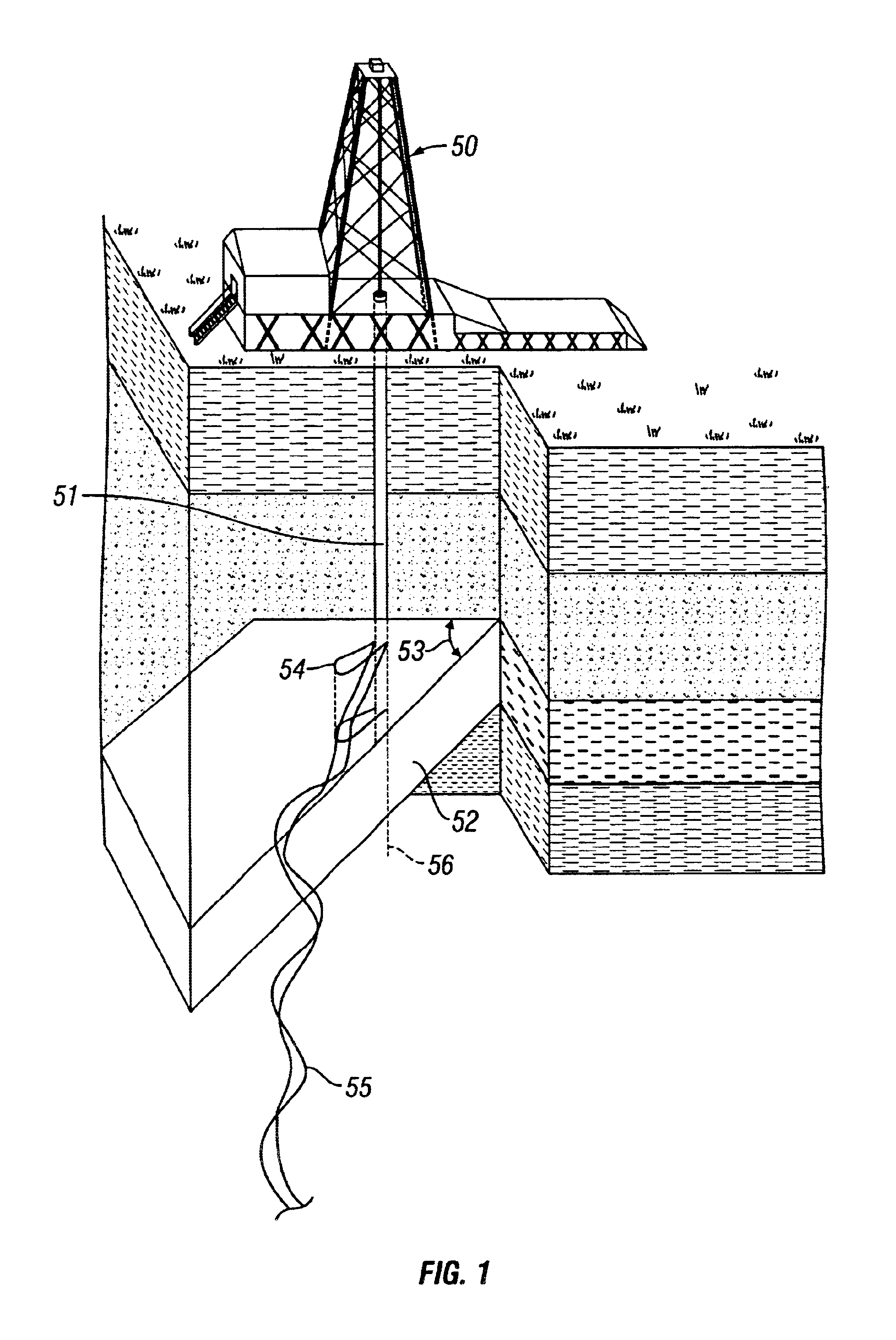
The complications described above are detailed in FIG. 1. As shown in FIG. 1, a typical drilling rig 50 attempting to drill a substantially vertical well 51. When the drill bit contacts a extra hard earthen formation 52 at an acute angel 53, the bit tends to drift across the surface of the extra hard earthen formation 52 creating an elongated hole 54 often described as the “key slotting” or “key holing” effect. Additionally, as additional weight is applied to the rotating drill string having torque applied thereto to penetrate the extra hard earthen formation 52, the drill bit tends to have a biting effect when it contacts such extra hard earthen formations 52. The rotation of the drill string pipe itself, coupled with the applied weight and torque, tends to bow the drill string pipe and causes the drill bit to take a spiral-like path 55 often referred to as the “corkscrew effect.” This spiral-like path 55 of the drill bit results in wasted drill string pipe, time, and extensive cos...


PUM


Abstract

A well borehole is prevented from deviating from its intended vertical path as it is being drilled by use of a sub assembly which is eccentrically weighted with respect to its axis of rotation. Such a sub assembly can comprise a straight tubular member weight relieved along one side by, for example, forming a cavity within the heavy walls of the tubular member along the side of the collar. Thus, the eccentric weight is imposed upon the drill bit without providing any protrusions or elbows which are designed to bear on the wall of the borehole. Additionally, as the cavity is contained within the heavy walls of the tubular member, drilling fluids containing various debris cannot inhabit the cavity, thus maintaining a constant eccentric weight upon the drill bit.

Description

BACKGROUND OF THE INVENTION1. Field of the InventionThis invention relates to drill strings employed in well drilling, and more particularity to a method and apparatus for drilling straight wells by preventing unwanted spiraling progressions and slotting effects generally associated with drilling through relatively irregular formations, specifically through extra hard earthen formations.2. Background of the InventionDrill string collars generally used in drilling operations consist of long columns of thick walled tubes directly above the drill bit. These collars add additional weight to the drill string pipe to push the rotating drill bit through earthen formations. These drill string collars are generally connected to the thousands of feet of drill string pipe connected thereabove. A rotary drilling rig turns the drill string pipe, which turns the drill collars, which turn the drill bits used in creating a well.It is well known in the drilling industry that when a drill bit comes i...

Claims


Application Information

Patent Timeline
Patent Type & Authority Patents(United States)
IPC IPC(8): E21B17/00E21B7/10E21B7/04E21B17/16
CPCE21B17/16E21B7/10
Inventor HINDS, CYRIL
Owner MATTHEWS FIRM THE
Why Eureka
Try Eureka