Differential mechanism for a vehicle

a technology of differential mechanism and differential mechanism, which is applied in the direction of electric propulsion mounting, transportation and packaging, gearing, etc., can solve the problems of not only the structure of the differential mechanism but also the torque split control are complicated, and achieve the effect of sufficient reliability

Inactive Publication Date: 2005-02-08
SUBARU CORP
View PDF9 Cites 7 Cited by
  • Summary
  • Abstract
  • Description
  • Claims
  • Application Information

AI Technical Summary

Benefits of technology

The present invention was made in view of these situations, and an object thereof is to provide a differential mechanism for a vehicle which can control a torque split and secure a sufficient level of reliability.
Consequently, since the torque split can be implemented through the electric power by using the input generator motor and the output generator motor, the torque split control can be facilitated and furthermore, a sufficient level of reliability can be secured when compared with the differential mechanism for the vehicle in which the torque split is implemented through, for example, a hydraulic pressure.
In addition, since the electric power generated by the rotational drive force of one of the input shaft and the one of the output shafts of the differential is designed to be supplied for use in the application of the rotational drive force to the other, the rotational drive force of the engine can effectively be used.
Additionally, in case either of the respective output shafts is racing, since the differential action of the differential is designed to be limited, a necessity can be obviated of separately providing a mechanism for limiting such a motion of the differential, which can provide a large advantage in practical use.
Consequently, since the torque split can be implemented through the electric power by using the electric motor and the output generator motor, the torque split control can be facilitated and furthermore, the sufficient level of the reliability can be secured when compared with the differential mechanism for the vehicle in which the torque split is implemented through, for example, the hydraulic pressure.
In addition, since the electric power generated by the rotational drive force of the one of the output shafts of the differential is designed to be supplied for use in the application of the rotational drive force by the electric motor, the rotational drive force of the electric motor can effectively be used.

Problems solved by technology

With the aforementioned differential mechanism, however, the control of the plurality of the clutches through the hydraulic pressure causes a problem that not only a structure of the differential mechanism but also the torque split control are made complicated.
In addition, on top of the complicated structure, there is also caused a problem with securing a sufficient level of reliability due to leakage and deterioration of oil used.

Method used


Image

  • Differential mechanism for a vehicle
  • Differential mechanism for a vehicle
  • Differential mechanism for a vehicle

Examples


first embodiment

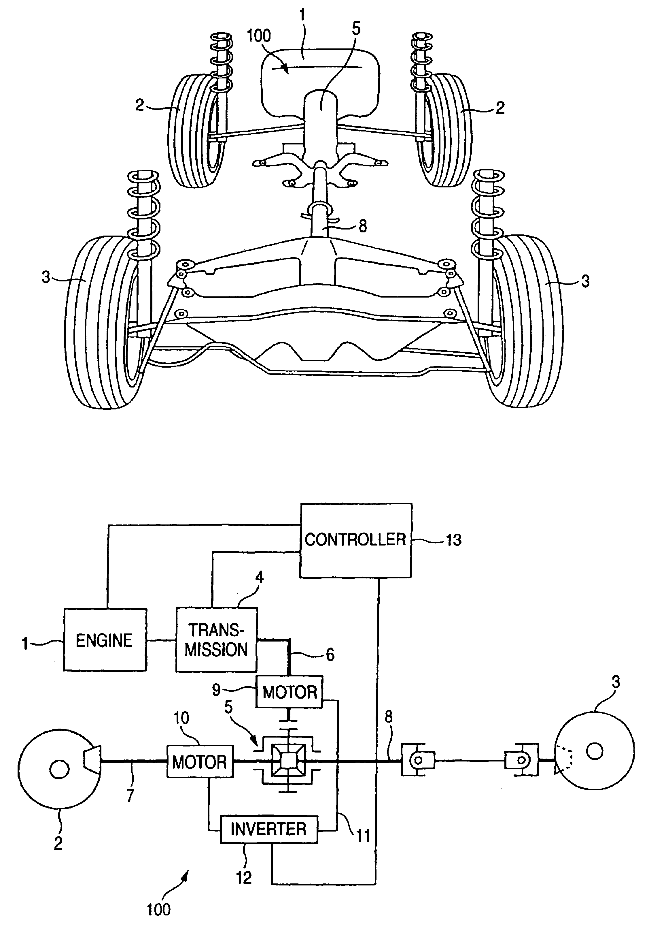
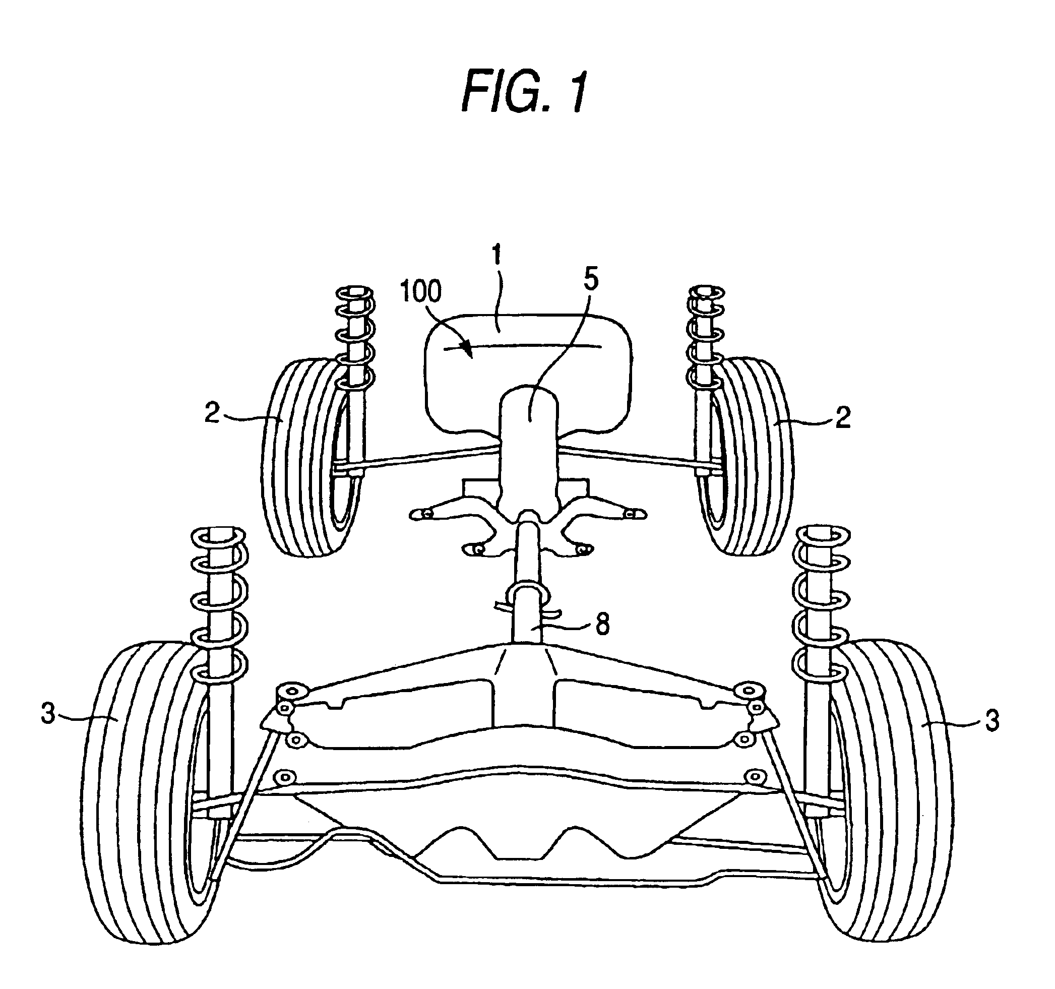
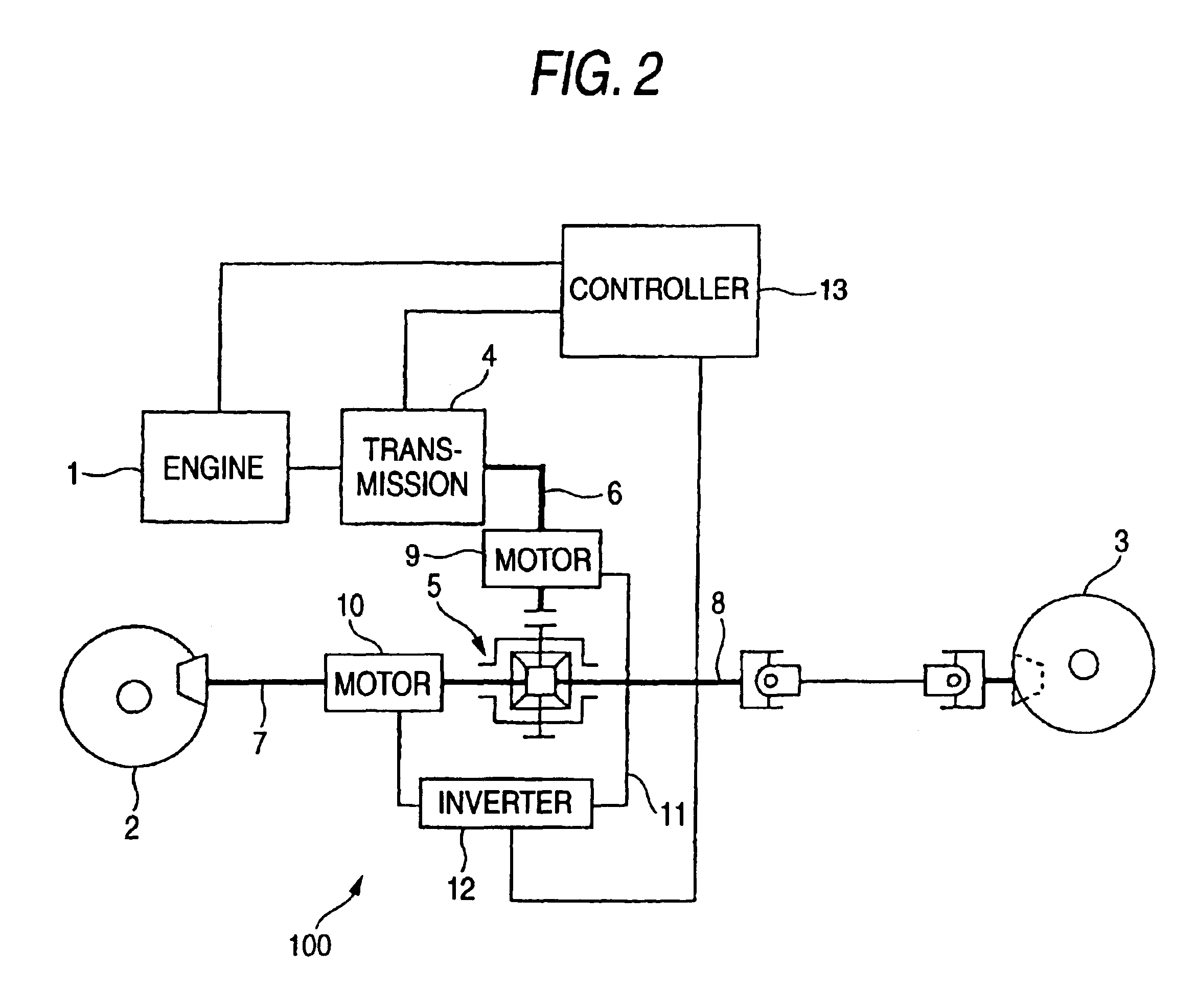
FIGS. 1 and 2 show the present invention, in which FIG. 1 is a schematic drawing showing a drive line for a vehicle and FIG. 2 is a schematic diagram showing a differential mechanism for the vehicle.

The vehicle is a so-called four-wheel drive (4WD) vehicle, and has, as shown in FIGS. 1 and 2, an engine 1 as a power source, and a drive force of the engine 1 is split (distributed) and transferred to front wheels 2 and rear wheels 3. The drive force of the engine 1 is carried (transmitted) to an input shaft 6 of a differential 5 via a transmission 4. In this embodiment, the differential 5 has a front output shaft 7 for transferring the rotational drive force to the front wheels 2 and a rear output shaft 8 for transferring the drive force to the rear wheels 3, and the respective output shafts 7, 8 are structured so as to rotate at different speeds. Namely, a differential mechanism 100 of the 4WD vehicle has the differential 5 comprising the input shaft 6 and the respective output shafts...


PUM


Abstract

A differential mechanism for a vehicle has: a differential for transferring a rotational drive force of an input shaft to two output shafts; an input generator motor for generating electric power using a rotational drive force of the input shaft and / or applying the rotational drive force to the input shaft using electric power supplied thereto; an output generator motor for generating electric power and applying a rotational drive force to the one of the output shafts; and connecting means for electrically connecting the input side generator motor with the output generator motor; switching control unit for switching between an output drive force control for supplying electric power generated by the input generator motor to the output generator motor and the input drive force application control for supplying electric power generated by the output generator motor to the input generator motor.

Description

BACKGROUND OF THE INVENTION1. Field of the InventionThe present invention relates to a differential mechanism for a vehicle, particularly to a 4WD vehicle with two auxiliary assist motors.2. Description of the Related ArtIn general, a differential is provided on a four-wheel drive (4WD) vehicle for splitting (dividing or distributing)and transferring a drive force of an engine to front and rear wheels. The differential has an input shaft to which a rotational drive force from the engine is transferred and output shafts to which the rotational drive force of the input shaft is transferred and which are allowed to rotate at different speeds. This provision of the differential allows the front and rear wheels to turn at the different speeds even if there occurs a difference in a turning speed between the front and rear wheels when the vehicle goes round a bend (corner), whereby the vehicle is allowed to run smoothly round the bend.In recent years, 4WD vehicles are known in which the to...

Claims


Application Information

Patent Timeline
Patent Type & Authority Patents(United States)
IPC IPC(8): B60K6/04B60K6/00B60K17/344B60K17/356B60K17/34B60K17/346F16H3/72F16H3/44B60K1/02B60K1/00B60K17/04B60K6/20B60K6/26B60K6/36B60K6/40B60K6/48B60K6/52B60K6/54B60L15/20B60W10/08B60W20/00
CPCB60K6/40B60K6/445B60K6/52B60K6/54B60K17/346B60K17/356B60W10/08F16H3/727B60K6/26B60K1/02Y02T10/6239B60K23/0808Y02T10/6265Y02T10/7258Y10S903/903Y10S903/951Y10S903/909Y10S903/906Y10S903/917Y10S903/916Y02T10/62Y02T10/72
Inventor SAKAZAKI, AKIHIKO
Owner SUBARU CORP
Why Eureka
Try Eureka