
Arrangement for determining a characteristic form of an input signal

a technology of input signal and characteristic form, applied in the direction of transmission system, modulated carrier system, transmission, etc., can solve the problem of limiting resources, affecting the accuracy of signal estimation, and compromising design, so as to achieve the effect of accurately estimating the frequency offs

Active Publication Date: 2011-03-03
QORVO INT PTE LTD
View PDF2 Cites 18 Cited by
  • Summary
  • Abstract
  • Description
  • Claims
  • Application Information

AI Technical Summary

Benefits of technology

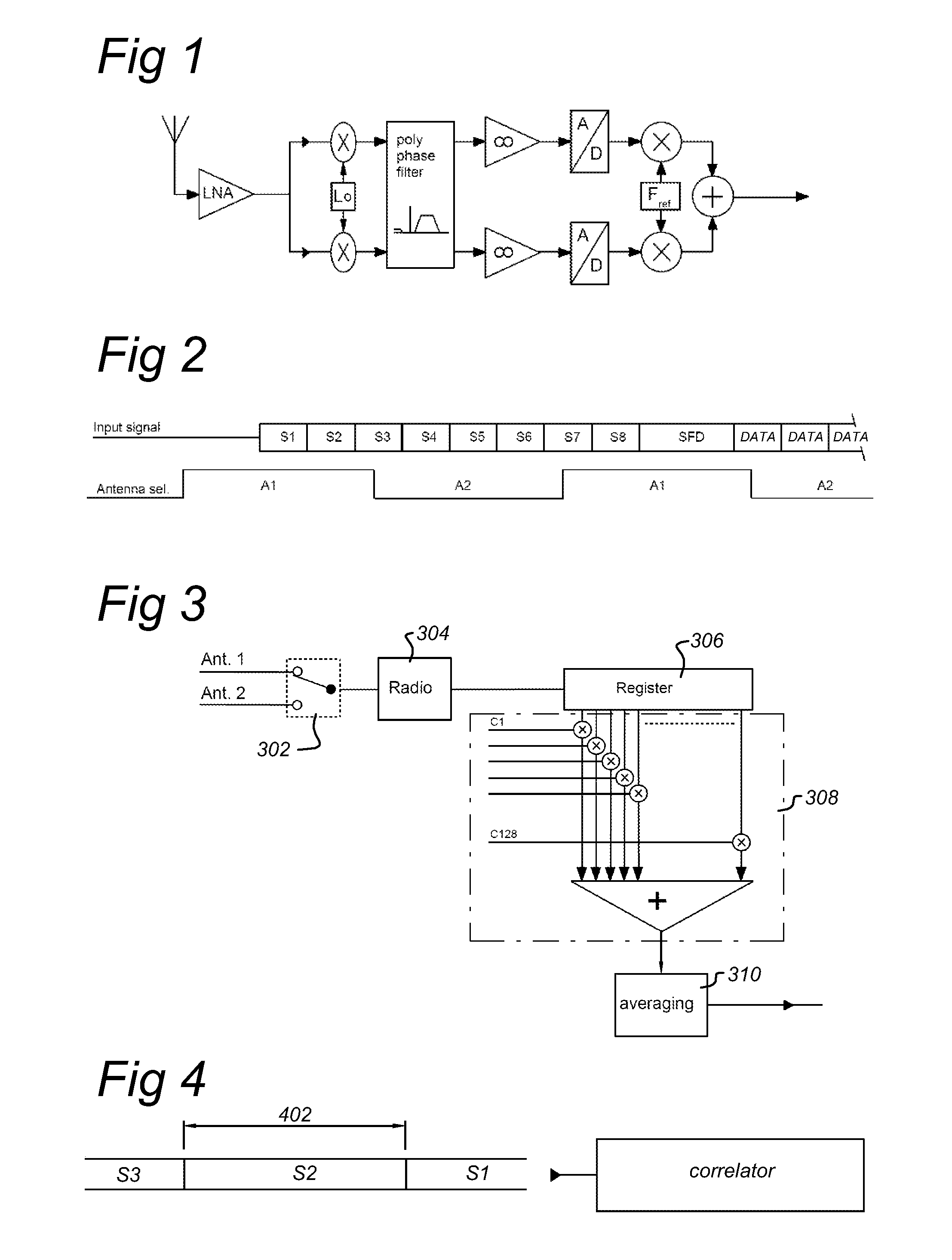
[0037]By means of the method according to the invention, from one preamble seven correlation values can be determined. In case of an antenna diversity system with two antennae and having a switching period approximating the symbol period, for one antenna four correlation values can be determined and for the other antenna three correlation values can be determined. Thus, when only one antenna delivers a signal of sufficient quality to detect a preamble, irrespective the timing offset of the antenna switching signal, for both antennae the three correlation values enable us to determine the distance between noise and a noisy preamble with a sufficiently reliable level, to ensure a reliable preamble detection.
[0047]With a low IF architecture, the IF frequency is still present at the input signal. Therefore, the contents of the shift register is a preamble signal subjected to the frequency offset equal to the IF frequency. Feeding the output of the shift register back to its input is only allowed if the phase rotation of the IF signal between input and output is not to large. Such a phase difference occurs when the IF of the signal is not a multiple of the symbol rate. When the IF frequency gives during the duration of a symbol interval an integer number of full phase rotations, then the given feedback gives no phase error. The choice of correlator centre frequencies, is either a multiple of the symbol rate or a multiple plus half the symbol rate. For the case the correlator centre frequencies is a multiple plus half the symbol rate, the second rotation unit is used where an sign-inverted version of the signal is feed back to the input. This inversion corresponds to a phase shift of 180 degrees, which corresponds to a phase rotation caused by an IF frequency which is an integer plus half multiple the symbol rate. These features enables us to detect a preamble signal in presence of larger frequency offsets and to estimate the frequency offset more accurately.
[0048]In an embodiment of the invention, a data symbol is a PN chip sequence wherein the chip rate approximates the IF-frequency. In a more specific embodiment, N / SP approximates 4×fIF. In a further embodiment, N=128 and fIF=2 MHz. In an exemplar embodiment, the input signal is a binary signal. These embodiments allow us to provides minimum implementation solutions, with respect to chip area and power dissipation.
[0059]Due to the fast and reliable carrier detection characteristics of the present invention under poor receiving conditions, the present invention is also very suitable for use in a system with multiple antennae. The invention allows us to provided during a period of eight symbols up to seven frequency offset and symbol timing estimations. For a system with two antennae, this will result in four estimations for one antenna and three estimations for the other antenna. This allows us to average the subsequent estimation results and to select the antenna providing the best reception of the signal.

Problems solved by technology

However in low power systems there are premiums and often limitations on resources, and any design must be compromised between the need for optimizing the performance and available resources.
In general, the preamble detection should be sufficiently reliable and not dominate the failure of received packets.
However, a single correlation result does not give a reliable distinction between a noise signal and a preamble signal in presence of noise (poor SNR).
However, this would be expensive in terms of chip area and in power consumption.
Consequently, the start of the preamble is missed, since there is insufficient time to detect the preamble.
The next slot does not result in preamble detection either, since antenna 2 does not deliver signal of sufficient quality.
The two SFD symbols which are different from preamble symbols, will not be recognized as preamble symbol, and do not provide correlation results for reliable preamble detection.
A problem here is that the symbol timing is not yet known, which means that generally in one symbol interval the last part of a symbol is captured and the beginning of the subsequent symbol.
This is insufficient for averaging over at least three correlation results for each antenna.

Method used


Image

  • Arrangement for determining a characteristic form of an input signal
  • Arrangement for determining a characteristic form of an input signal
  • Arrangement for determining a characteristic form of an input signal

Examples


first embodiment

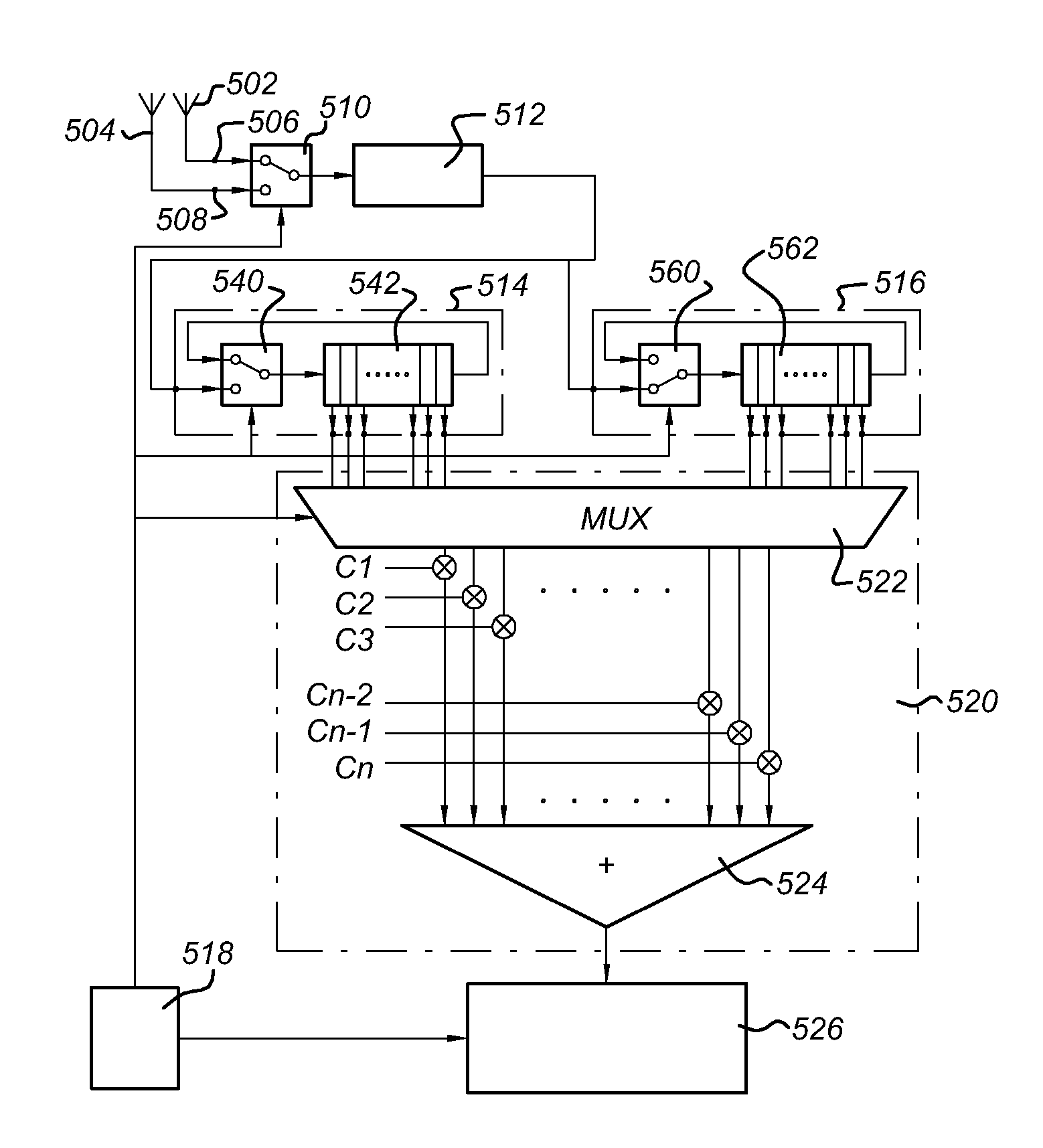
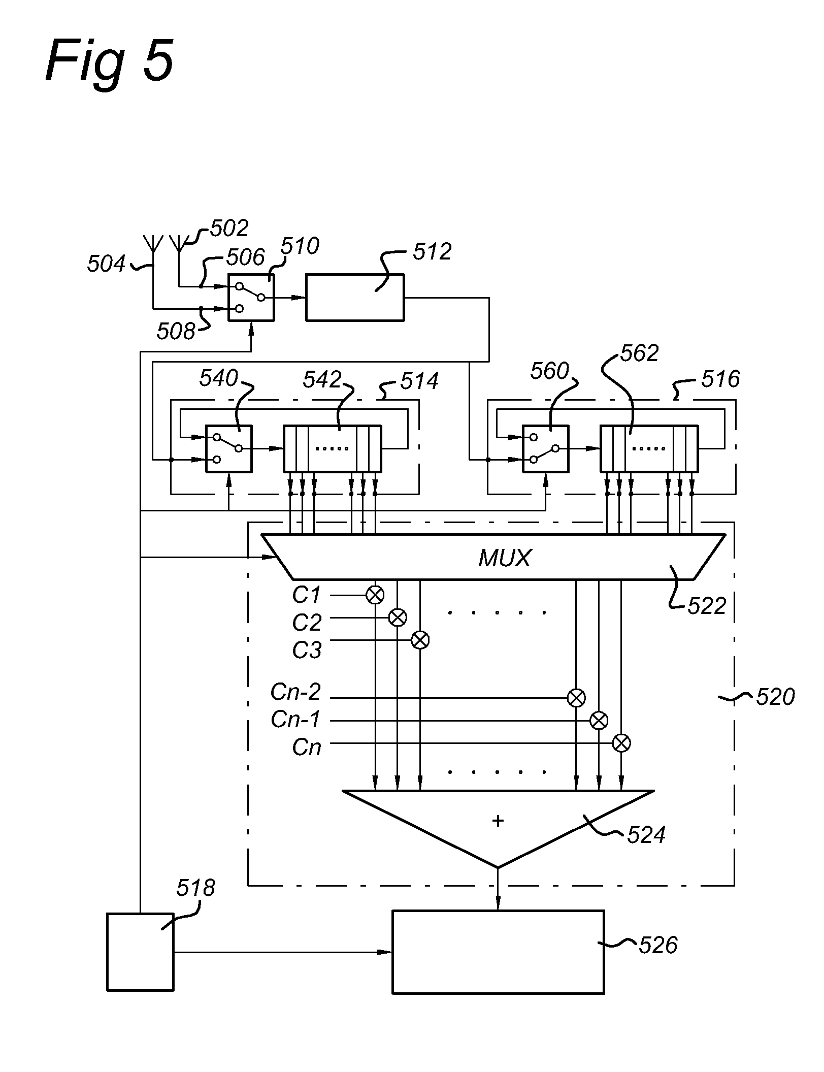
[0088]FIG. 5 shows a simplified block diagram of a receiver according to the invention. The receiver comprises in this embodiment comprises a first and second input terminal 506, 508 coupled to antennae 502, 504 respectively for retrieving a first and second antenna signal. A first multiplexer 510 comprises a first and second input coupled to the first and second input terminal respectively, and a control signal input for retrieving a control signal. The multiplexer being arranged for selecting the first and second antenna signals one by one under control of the control signal so as to obtain a combined antenna signal. The combined antenna signal is supplied to a radio unit 512, as shown in FIG. 1. The radio unit 512 converts the combined antenna signal into a digital IF signal. The digital IF signal is sampled with a sample frequency fSF. The sample frequency is preferably a multiple of the symbol rate or the chip rate in case a symbol is a PN sequence. In the present embodiment, t...

second embodiment

[0105]FIG. 10 shows a simplified block diagram of a combination of rotation units and correlation unit as shown in FIG. 5. Input terminal 1002 is coupled to the output of a radio unit 512 as shown in FIG. 5. The input terminal 1002 receives a digital IF signal having a sample frequency fSF. The combination shown in FIG. 10 comprises a first and a second rotation unit 1004, 1006 and a correlation unit 1008. Each rotation unit has an input, a control signal input (not shown) and an output. The input is arranged for receiving N subsequent samples of the input signal under control of the control signal. The N subsequent samples represent a part of the input signal approximating a symbol period SP. The rotation units 1004, 1006 being arranged for rotating the N subsequent samples to generate N rotated output signals. The first rotation unit 1004 is arranged to receive under control of a control signal (not shown) from the digital IF signal samples corresponding to a first antenna signal ...


PUM


Abstract

A receiver and method for determining a characteristic from an input signal is disclosed. A characteristic is at least one selected from a group comprising preamble detect, frequency offset and timing offset. The input signal comprises an IF frequency fIF and a preamble signal which is a sequence of M similar data symbols. The data symbols have a symbol period SP, and M is an integer greater than or equal to 2. The method comprises: -receiving N subsequent samples of the input signal, the N subsequent samples representing a part of the input signal approximating the symbol period SP, -rotating N subsequent samples to obtain N rotated symbols; -correlating the N rotated symbols with P correlation functions to generate a set of N×P correlation values, P being an integer greater than or equal to 2; and, -selecting a maximum correlation value from the set of N×P correlation values and determining the characteristic. The invention enables to perform an efficient antenna diversity circuit, which can be used for simultaneously timing offset and frequency offset estimation, and preamble detection for both antennae with only one radio unit.

Description

FIELD OF THE INVENTION[0001]The present invention relates to an arrangement for determining a characteristic from an input signal. In a further aspect the invention relates to a receiver for estimating a timing offset and frequency offset. In a further aspect, the present invention relates to a method for estimating a timing offset and frequency offset. In yet a further aspect, the present invention relates to a method for preamble detection and antenna diversity selection.[0002]The invention has particular application in wireless infrastructure employing wireless communication devices in which power consumption of the whole infrastructure or power consumption of a battery powered device is an issue. ZigBee, Bluetooth and IEEE 802.11 (“WiFi”) are examples of wireless protocols that could be used.PRIOR ART[0003]Such a receiver is known to be used in a low data rate wireless communication network, e.g. operating according to the ZigBee standard (using the IEEE 802.15.4 Medium Access C...

Claims


Application Information

Patent Timeline
Patent Type & Authority Applications(United States)
IPC IPC(8): H04L12/26H04B1/707
CPCH04L2027/0034H04L2027/0095H04L2027/0028H04L7/042H04B1/7075
Inventor VAN DRIEST, HANSLUBBERHUIZEN, WESSEL HARM
Owner QORVO INT PTE LTD
Learn More