Threaded pipe joint

a technology for threaded pipes and joints, which is applied in the direction of threaded joints, pipes/joints/fittings, hose connections, etc., can solve the problems of structural needs in the use of pipes which cannot be satisfied, serious economic consequences, and environmental damag

Inactive Publication Date: 2005-02-08
TENARIS CONNECTIONS BV A CO EXITING & ORGANIZED UNDER THE LAWS OF THE NETHERLANDS +1
View PDF28 Cites 45 Cited by
  • Summary
  • Abstract
  • Description
  • Claims
  • Application Information

AI Technical Summary

Problems solved by technology

There are structural needs in the use of the pipes which cannot be satisfied by those pipes normally designed for vertical wells.
Reducing the causes of breakage of the joints to a minimum is vitally important, as the breakage of pipes, especially after being laid underground, therefore making it almost impossible for the operators to intervene directly on the joint that may have broken, can have serious economic consequences on the extraction plant and cause considerable environmental damage, especially in the event that the reservoir contains aggressive elements.
The structural and sealing problems are often made worse by the temperature of the fluids, their corrosiveness or the existing environmental conditions in the mining area.
The pipes' required resistance to compression, especially in the threaded joint area is therefore a much felt need, and often the weakness of the joints is a weak point of this type of technology.
Similar unfavourable conditions also occur in the strings when they are used to inject steam, due to the high thermal loads.
In particular circumstances, for example, for very sloping angles of the lead-in flank of the thread, measured compared to a perpendicular surface to the pipe's axis, the compression action of the string is unsatisfactory, as this type of solution aids the onset of the phenomenon defined as “jump-in”, when the compression forces exceed certain limits.
Another drawback of this type of thread is that it is subject to high risk of seizure of the joint with the consequent risk of not ensuring the airtight seal of the fluids, upon bearing, a torque that varies greatly as the screwing operation of the joint proceeds and more turns are mutually involved.
This introduces difficulties in making the joint and creates the possibility of imprecision in applying the correct driving torque.
This involves an increase in the processing of the ends of the pipes, which requires, in particular, before putting them through the threading process, a processing for permanent set, with the consequent stress-relieving treatment to eliminate residual stress, with a consequent increase of costs and time for production.
However, also in this case, the results are not always satisfactory as in the best of cases the compression resistance obtained in this way at the joint point never exceeds 70% of the resistance of the non-threaded part of the pipe segment.

Method used


Image

  • Threaded pipe joint
  • Threaded pipe joint

Examples


Embodiment Construction

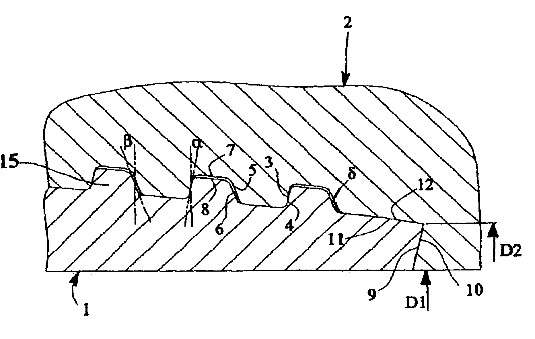
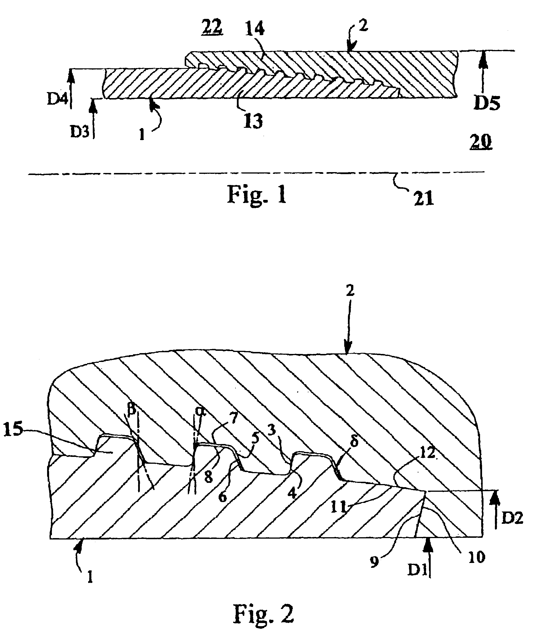
With reference to the drawings, a joint according to the present invention is now described by way of non-limiting example.

The joint shown in the figures comprises two members, i.e. the male 1 and the female 2. In this case, the male member is a pipe, generally male threaded at both ends, and the female member is a sleeve female threaded at both ends and joins two pipes, by means of two joints as described. The joint defines an inner part 20, containing the axis 21 of the pipe segments 1 and 2, in which the fluid, for example natural gas or petroleum or other similar fluid, flows, and an outer part 22 in which there can be fluids of various kinds, which are also generally pressurised. The external diameter D4 of the pipes, in the area not involved in the joint between the male member and female member can be smaller than the external diameter D5 of the end of the female member in the joint area of a value that varies from 0% in the event of an integral “flush” type joint up to aroun...


PUM


Abstract

Threaded joint for pipes consisting of a male member (1) and a female member (2), which are provided on the outer and inner surfaces respectively with two threading portions presenting a lead-in flank β such that 10°≦β≦25°, an abutment surface (9) being present at the end of said male member for abutment to a corresponding annular abutment surface (10) of the female member. The lead-in flanks of the male (1) and the female (2) members, upon make-up and with unloaded joint leave a gap (in the direction parallel to the axis (21) of the joint) varying from 0.01 to 0.12 mm. The internal and external diameters D3 and D4 (of the pipe portion not involved in the coupling with the female member) of said male member, the inner and outer diameters D1 and D2 of the abutment surface of the female member are linked by the relationship: (D22−D12) / (D42−D32)≧0.5.

Description

FIELD OF THE INVENTIONThe present invention generally relates to a threaded joint for pipes, in particular joints for pipes used in the gas or oil exploitation industry. These pipes can be used both as tubings for the pumping of gas or petroleum, and as casing of the drilling wells themselves.STATE OF THE ARTIn the natural gas and oil extraction industry, pipes of pre-defined length are used, which must be joined to each other at their ends to be able to reach the great depths where the hydrocarbon fields are usually located.The drilling technique most commonly used is that of drilling, by means of boring, wells that start from land level or sea level until reaching the gas or oil reservoir. The depth of these wells can reach several thousand meters. During boring, the wells are lined with metal pipes along their whole length. The metal pipe segments, about ten meters long, are joined together by means of threaded joints. Therefore, these pipes form a tubular string, with a constant...

Claims


Application Information

Patent Timeline
Patent Type & Authority Patents(United States)
IPC IPC(8): F16L15/06F16L15/00F16L15/04
CPCF16L15/004
Inventor CARCAGNO, GABRIEL E.PINA, GIUSEPPE DELLATOSCANO, RITA G.COPPOLA, TOMMASO
Owner TENARIS CONNECTIONS BV A CO EXITING & ORGANIZED UNDER THE LAWS OF THE NETHERLANDS
Why Eureka
Try Eureka