Continuous ink-jet printing apparatus having an improved droplet deflector and catcher

a technology of droplet deflector and droplet catcher, which is applied in the field of digital control printing devices, can solve the problems of large spatial volume, complex printers, and large components of continuous ink jet printheads, and achieve the effects of improving the ability to remove non-printed ink droplets and the angle of droplet deflector

Inactive Publication Date: 2005-02-08
EASTMAN KODAK CO
View PDF15 Cites 199 Cited by
  • Summary
  • Abstract
  • Description
  • Claims
  • Application Information

AI Technical Summary

Benefits of technology

An object of the present invention is to provide an ink jet printhead having improved ink droplet deflection angles and improved non-printed ink droplet removal capabilities.

Problems solved by technology

As conventional continuous ink jet printers utilize electrostatic charging devices and deflector plates, they require many components and large spatial volumes in which to operate.
This results in continuous ink jet printheads and printers that are complicated, have high energy requirements, are difficult to manufacture, and are difficult to control.
Such a system is difficult to control and to manufacture.
Furthermore, the physical separation or amount of discrimination between the two droplet paths is small further adding to the difficulty of control and manufacture.
Such a system is difficult to manufacture and accurately control resulting in at least the ink droplet build up discussed above.
Furthermore, the physical separation or amount of discrimination between the two droplet paths is erratic due to the precise timing requirements increasing the difficulty of controlling printed and non-printed ink droplets resulting in poor ink droplet trajectory control.
Additionally, using two pneumatic deflectors complicates construction of the printhead and requires more components.
The additional components and complicated structure require large spatial volumes between the printhead and the media, increasing the ink droplet trajectory distance.
Increasing the distance of the droplet trajectory decreases droplet placement accuracy and affects the print image quality.
While this device works extremely well for its intended use, the angle of ink drop deflection is relatively small.

Method used


Image

  • Continuous ink-jet printing apparatus having an improved droplet deflector and catcher
  • Continuous ink-jet printing apparatus having an improved droplet deflector and catcher
  • Continuous ink-jet printing apparatus having an improved droplet deflector and catcher

Examples


Embodiment Construction

The present description will be directed in particular to elements forming part of, or cooperating more directly with, apparatus in accordance with the present invention. It is to be understood that elements not specifically shown or described may take various forms well known to those skilled in the art.

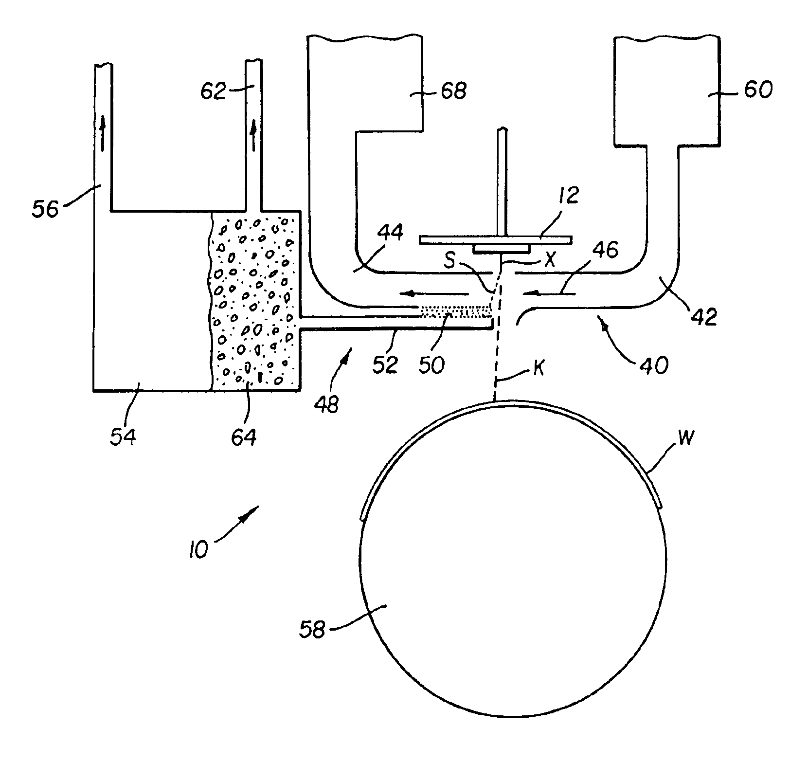
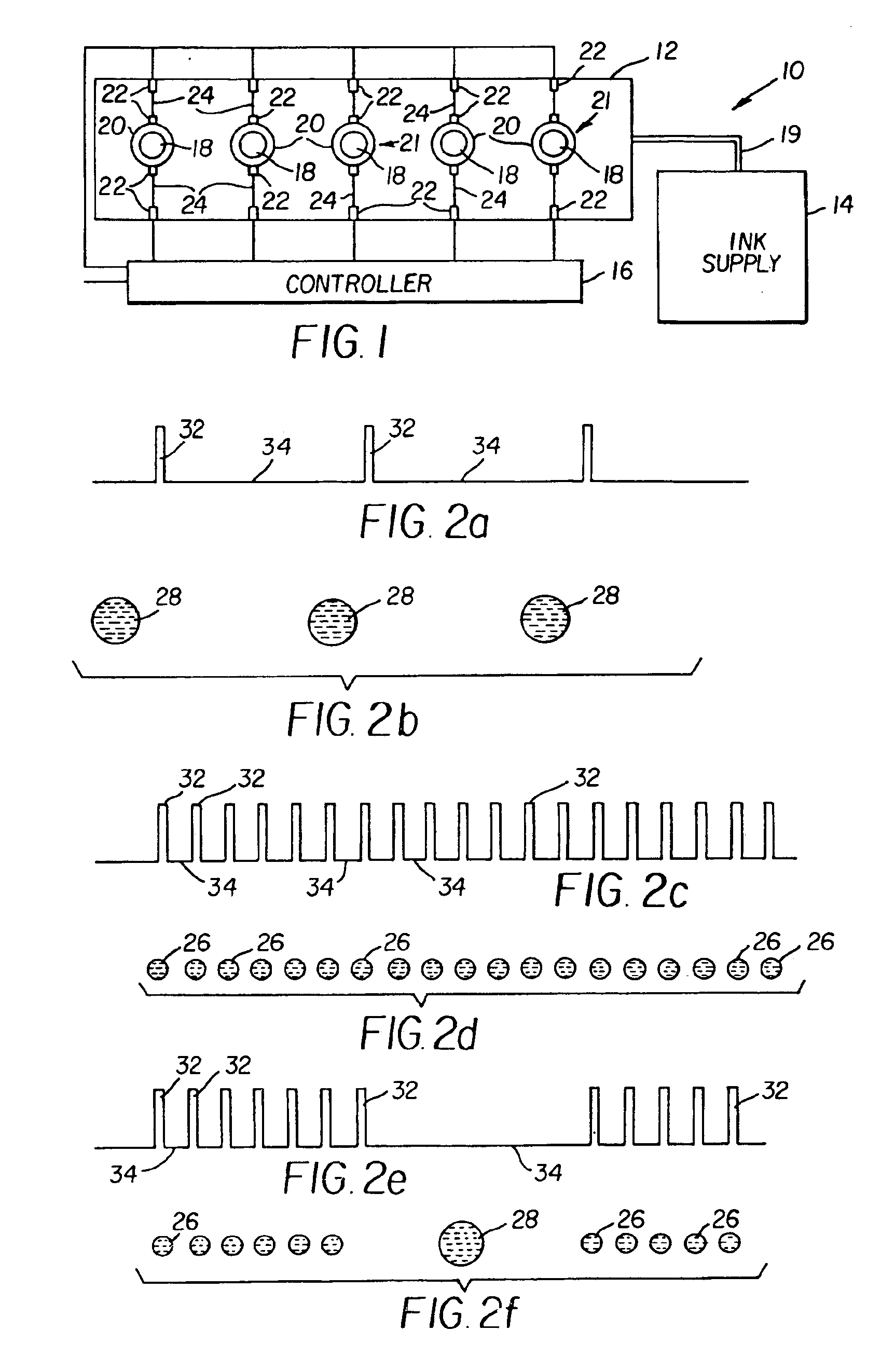
Referring to FIG. 1, a printing apparatus 10 of a preferred embodiment of the present invention is shown. Printing apparatus 10 includes a printhead 12, at least one ink supply 14, and a controller 16. Although printing apparatus 10 is illustrated schematically and not to scale for the sake of clarity, one of ordinary skill in the art will be able to readily determine the specific size and interconnections of the elements of the preferred.

In a preferred embodiment of the present invention, printhead 12 is formed from a semiconductor material (silicon, etc.) using known semiconductor fabrication techniques (CMOS circuit fabrication techniques, micro-electro mechanical structure (MEMS...


PUM


Abstract

An apparatus for printing an image is provided. The apparatus includes an ink droplet forming mechanism operable to selectively create a stream of ink droplets having a plurality of volumes traveling along a first path. A droplet deflector is positioned at an angle with respect to the stream of ink droplets. The droplet deflector includes a gas flow operable to interact with the stream of ink droplets such that ink droplets having one of the plurality of volumes begin traveling along a second path and ink droplets having another of the plurality of volumes begin traveling along a third path. At least a portion of a catcher including a porous material is at least partially positioned in one of the first, second, and third paths.

Description

FIELD OF THE INVENTIONThis invention relates generally to the field of digitally controlled printing devices, and in particular to continuous ink jet printers in which a liquid ink stream breaks into droplets, some of which are selectively deflected.BACKGROUND OF THE INVENTIONTraditionally, digitally controlled printing capability is accomplished by one of two technologies. The first technology, commonly referred to as “drop-on-demand” ink jet printing, provides ink droplets for impact upon a recording surface using a pressurization actuator (thermal, piezoelectric, etc.). Selective activation of the actuator causes the formation and ejection of a flying ink droplet that crosses the space between the printhead and the print media and strikes the print media. The formation of printed images is achieved by controlling the individual formation of ink droplets, as is required to create the desired image. Typically, a slight negative pressure within each channel keeps the ink from inadve...

Claims


Application Information

Patent Timeline
Patent Type & Authority Patents(United States)
IPC IPC(8): B41J2/03B41J2/015B41J2/09B41J2/075
CPCB41J2/03B41J2/09B41J2202/16B41J2002/033B41J2002/031
Inventor JEANMAIRE, DAVID L.HAWKINS, GILBERT A.FAISST, JR., CHARLES F.GARBACZ, GREGORY J.
Owner EASTMAN KODAK CO
Why Eureka
Try Eureka