Connection device for an electronic box

Inactive Publication Date: 2005-02-08
SIEMENS AG
View PDF6 Cites 28 Cited by
  • Summary
  • Abstract
  • Description
  • Claims
  • Application Information

AI Technical Summary

Benefits of technology

The fact that this central unlocking rib is thicker than the locking hooks allows the tab to pivot sufficiently for the locking hooks to escape the catching stops on the module.
According to another advantageous feature of this device, the piece for unlocking the connection module is extended by two symmetrical branches that are articulated to the piece about axes perpendicular to the mating plane of the box and of the module, the free ends of the branches being engaged in two

Problems solved by technology

In practice, there are several difficulties.
Firstly, the operator does not know exactly where to engage the tool, since the configuration of the locking tab provides several slots in the upper face of the assembly formed by a box and a module.
If the screwdriver is engaged on

Method used


Image

  • Connection device for an electronic box
  • Connection device for an electronic box
  • Connection device for an electronic box

Examples


first embodiment

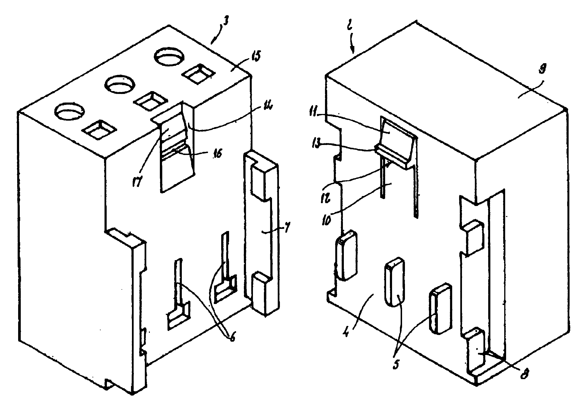
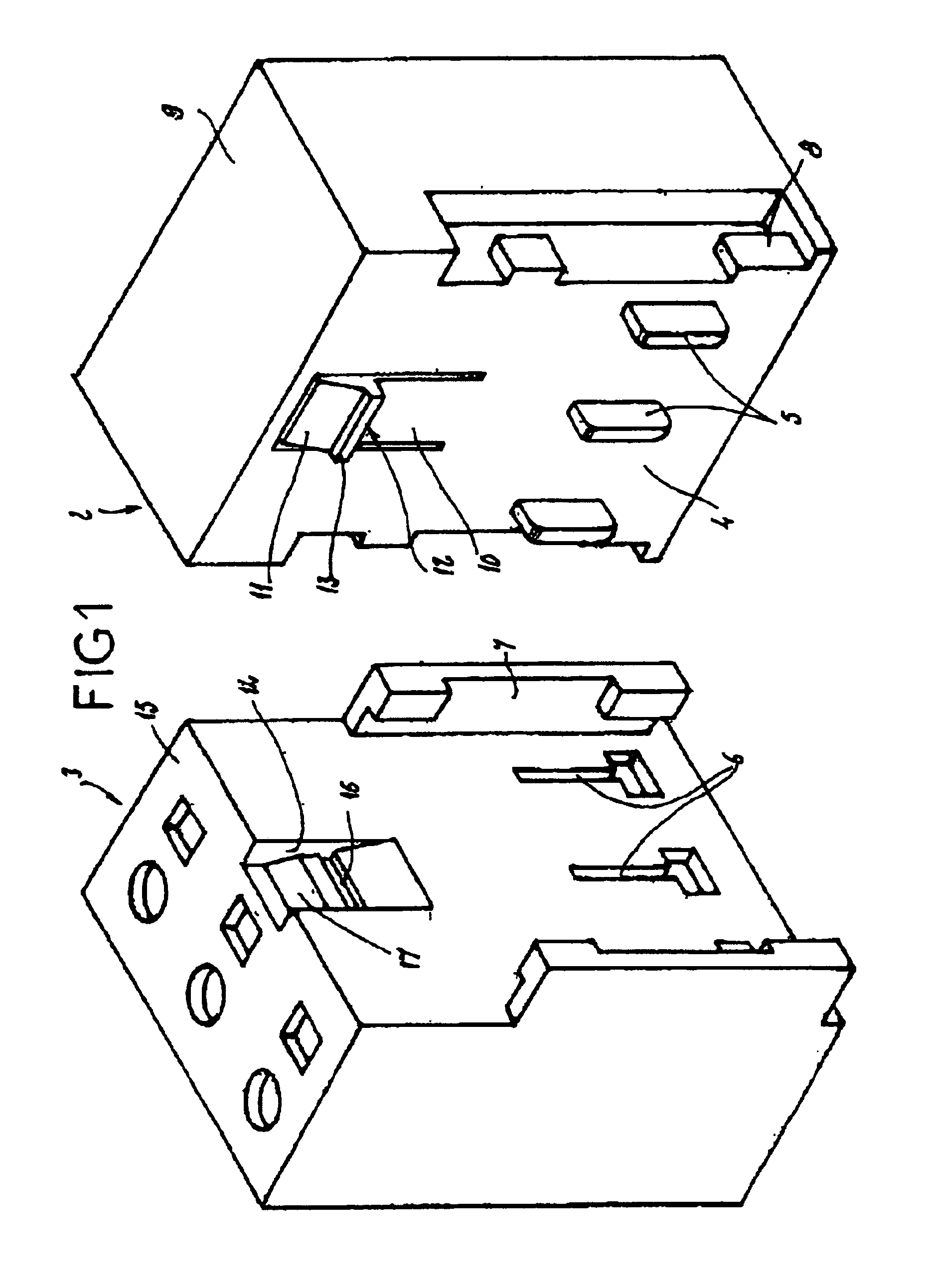
In the first embodiment shown in FIGS. 1 and 2, the box has, on its mating face and near its upper face 9, a resilient tab 10 having a hook 12 formed by a horizontal rib 13. Between the upper face of the box and the rib 13, the hook 12 has an inclined surface 14 angled downward and outward.

It should be noted that the notions of upper face of the box and of the module are relative positions used conventionally in the present description. It goes without saying that it will be possible for the face 9 of the box not to be the upper face if the box were to occupy another position in space.

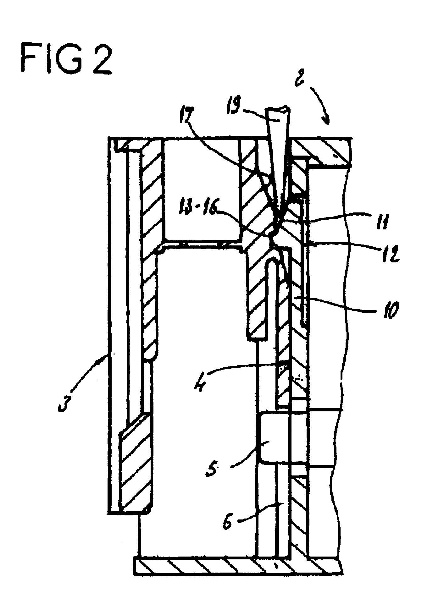
The connection module 3 has, in its mating face, a recess 14 opening into its upper face 15. Provided in this recess is a transverse groove 16 intended to accommodate the rib 13 of the hook 12. Provided above the groove 16 is a surface 17 inclined downward and outward.

FIG. 2 shows a sectional view of the box and the module in the mated position. It is apparent from this figure that, in the mating posit...

second embodiment

FIGS. 3 to 6 show this device, in which the same elements are denoted by the same reference numbers as previously.

In this device, the module 3 has, in its mating face, a recess 22 in which an unlocking piece, comprising a stud 23, is mounted so as to slide. Articulated to the stud 23 at 24 is a rigid arm 25, the free end 26 of which is engaged between a bottom stop 27 and a top stop 28. When the module is in the locking position on the box, the bottom stop 27 serves to catch an elastically deformable hook 29 mounted on the box. When the module is mounted on the box, as is the case in the embodiment shown in FIG. 4, a stop 30 protruding from the mating face of the box is located slightly below the bottom stop 27 of the module. FIG. 4 shows the module in the mated position on the box. In this position, the hook 29 is engaged behind the bottom stop 27. When the operator exerts vertical pressure on the sliding stud 23, the latter is pushed into the recess 22 and the arm 25 pivots at the...

third embodiment

FIGS. 7 to 11 show this device, in which the same elements are denoted by the same reference numbers as previously.

In this case, the box 2 has, in its mating face, an elastically deformable tab 32 located approximately at mid-width of this face and comprising two locking hooks 33 situated on either side of a central unlocking rib 34. The central unlocking rib extends beyond the two hooks 33. Each hook 33 has from the top down an engagement surface 35 inclined downward and outward and an engagement surface 36 for the purpose of locking, perpendicular to the mating plane of the box and of the module. The mating face of the box 2 has, below the tab 32, two symmetrical fixed stops 37.

The connection module 3 includes, in its mating face, an unlocking piece 38 mounted so as to slide parallel to the mating plane and accessible from the upper face of the module. This unlocking piece has a central drive rib 39 having a surface 40 inclined downward and inward, intended to bear, during unlocki...


PUM


Abstract

This device comprises a connection module (3) intended to be coupled with the longitudinal mating face of a box (2) and making an electrical connection with, on the one hand, pins protruding from this longitudinal mating face and, on the other hand, with conducting cables, the module (3) and the box (2) being mated by a system of slides (7, 8) allowing them to be fastened by longitudinal sliding, with locking by a resilient tab (10).
The resilient tab (10) is associated with the box (2) and is intended to cooperate with a locking member (16) associated with the connection module (3).

Description

BACKGROUND OF THE INVENTIONThe subject of the present invention is a connection device for an electronic box.DESCRIPTION OF THE PRIOR ARTElectronic boxes used in the industrial field are generally mounted in cabinets and are juxtaposed on one and the same rack, it being possible for several racks to be superimposed. These boxes possess a parallelepipedal general shape and each has one or more connection pins for connecting them to conducting cables that are connected to various types of equipment, such as timepiece systems, relays or signal processing equipment.Since in general a box is accessible only via a longitudinal face, connection to the conducting cables is accomplished by means of connection modules each fixed to the longitudinal mating face of a box. A connection module contains connection pieces with flat pins extending beyond the box, and a device for fastening the conducting cables, this being intended to be linked with these pins. It is known to fasten a connection mod...

Claims


Application Information

Patent Timeline
IPC IPC(8): H02B1/26H02B1/00H01R9/24
CPCH02B1/26H01R9/2408
Inventor LAFRAGETTE, PASCALCISEY, JOHANNDOUTAZ, LUC
Owner SIEMENS AG
Why Eureka
Try Eureka