
Method of manufacturing a sponge device

a manufacturing method and sponge technology, applied in the field of sponge manufacturing methods, can solve the problems of waste of sponge materials, high cost of multiple cutting and handling steps, and high labor intensity, and achieve the effect of a finished sponge surfa

Inactive Publication Date: 2005-02-08
MEDSORB DOMINICANA
View PDF17 Cites 7 Cited by
  • Summary
  • Abstract
  • Description
  • Claims
  • Application Information

AI Technical Summary

Benefits of technology

It is an object of the present invention to provide a method of making a sponge by casting so that no float away is created during manufacturing and which results in the creation of a smoother finished surface than prior art methods.

Problems solved by technology

One disadvantage with the present process is that it is very labor intensive, and the multiple cutting and handling steps are expensive.
Another disadvantage with the present process is that the multiple cutting steps cause some debris to be left on the sponge, which is referred to in the trade as “float away.” No matter how much effort is made to clean up the sponge, some of the debris from the cutting process remains embedded and has the potential to come loose when the sponge is wetted at the time of use.
This creates contamination, which, of course, is undesirable in medical applications.
Still further, the float away problem is exacerbated by the final step in the conventional manufacturing process.
Another disadvantage is that even if nearly all of the debris is removed from the finished sponge the cutting process leaves an inherently “rough” surface while a smoother surface is preferred.

Method used


Image

  • Method of manufacturing a sponge device
  • Method of manufacturing a sponge device
  • Method of manufacturing a sponge device

Examples


Embodiment Construction

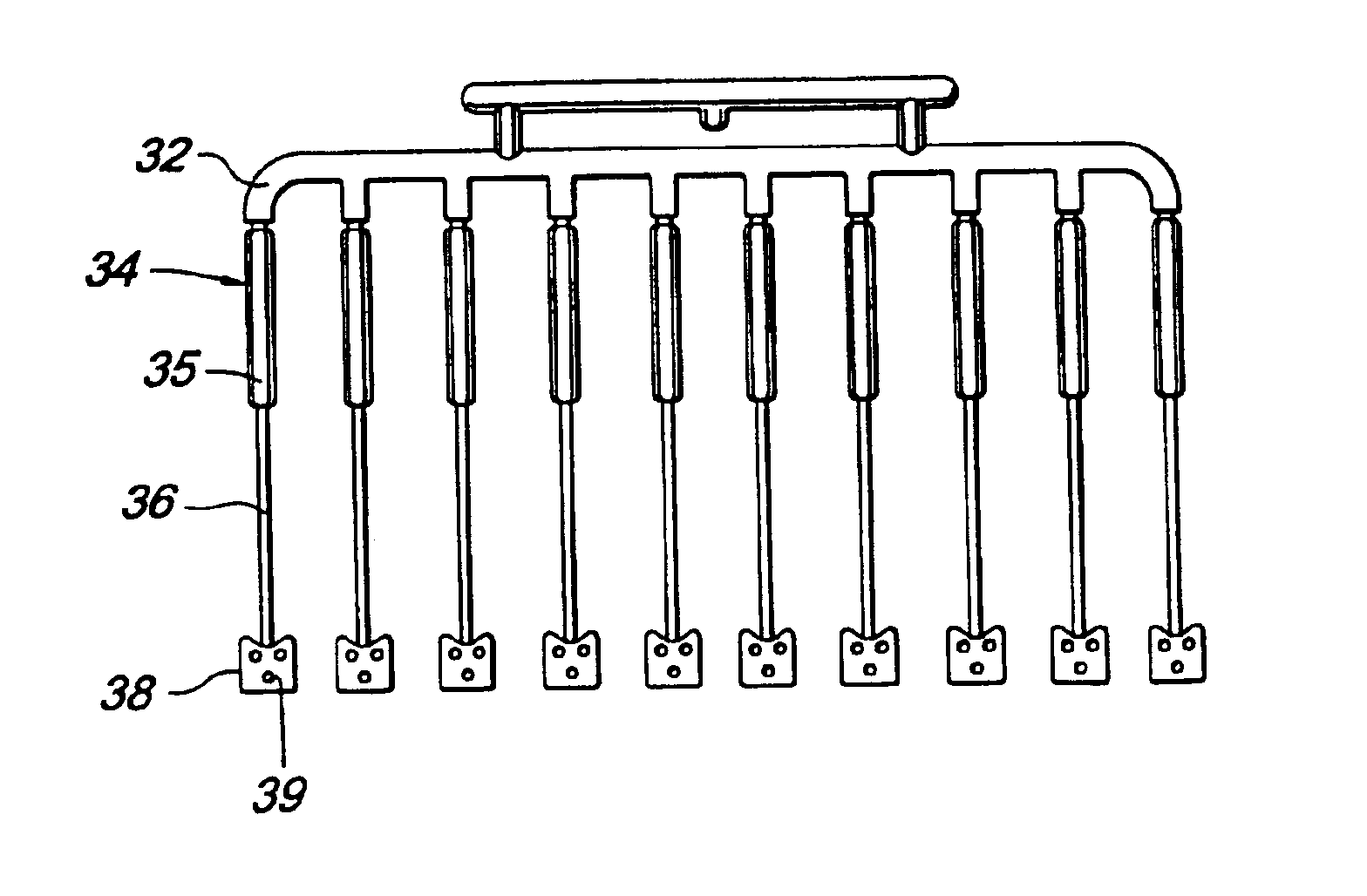
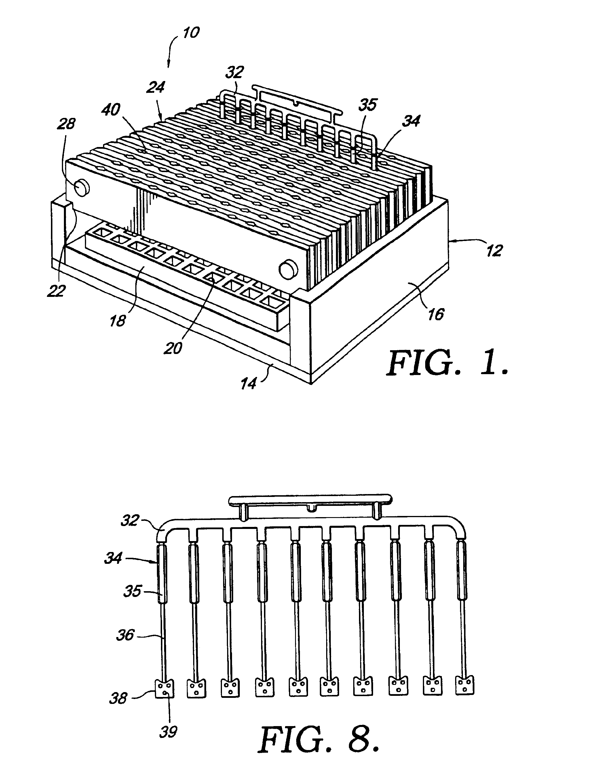
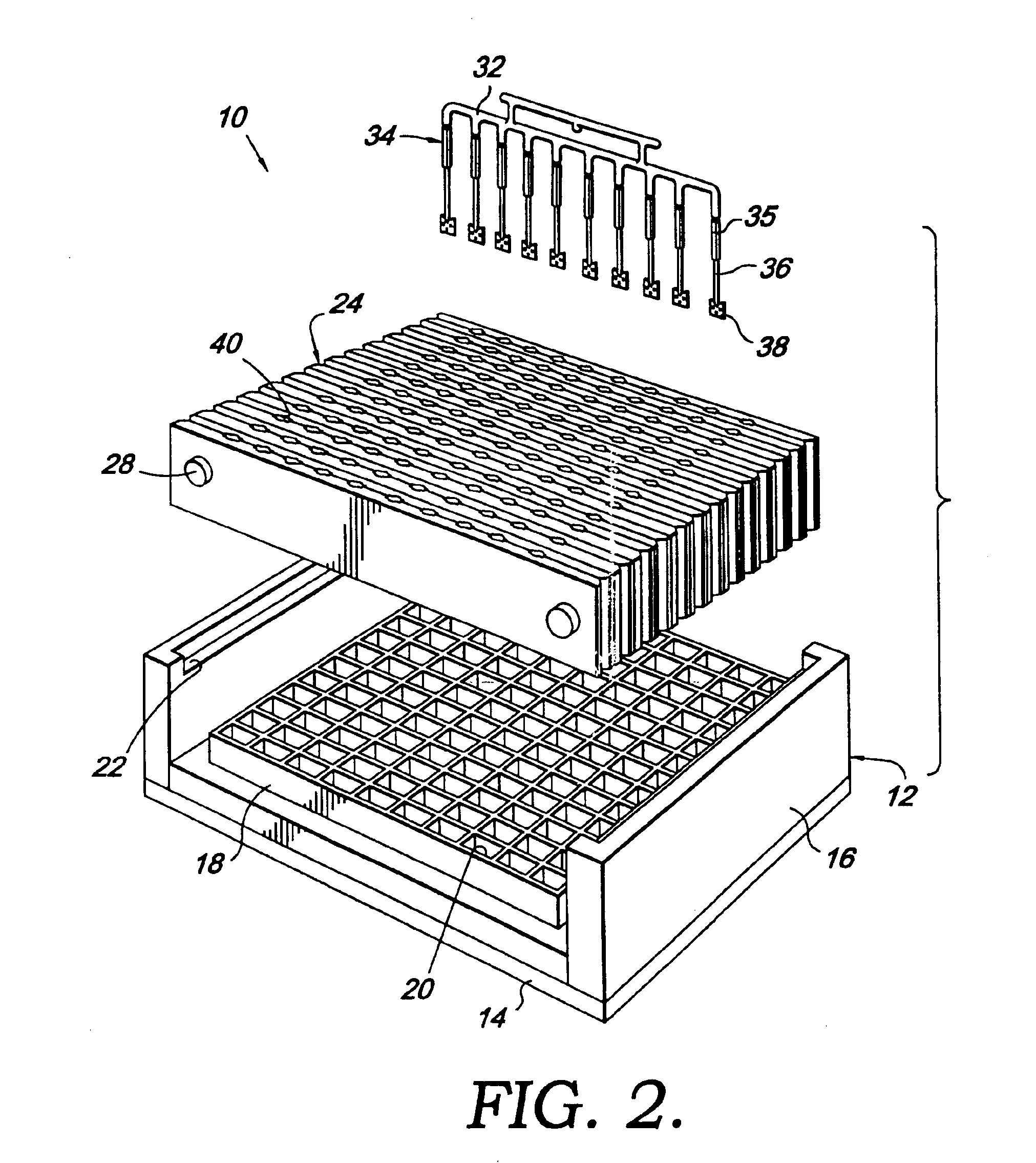
Referring to FIGS. 1 and 2, an assembly of the present invention is broadly designated by reference numeral 10. Assembly 10 includes a chase 12 having a bottom 14 coupled with sides 16. Assembly 10 also includes a form 18 that rests on bottom 14 of chase 12. Form 18 has cavities 20 therein for forming the sponge devices of the present invention. Chase 12 and form 18 are further shown in FIG. 7. Chase 12 has shelves 22 in its sides 16 for supporting and precisely placing plates 24, which are fastened together with rods 26 or other tubular members and caps 28, as shown in FIGS. 1, 4 and 5. More specifically, plates 24 have openings therein for receiving rods 26, and they are held in substantially planar alignment by the rods. As shown in FIG. 5, a spring 30 is within each rod 26 so that plates 24 can be spring-biased together. Plates 24 can be separated in a direction substantially perpendicular to the parallel planes formed by plates 24 by extending spring 30, which exposes rod 26, a...


PUM

PropertyMeasurementUnit
humidityaaaaaaaaaa
humidityaaaaaaaaaa
temperatureaaaaaaaaaa

Abstract

A method of making a sponge device is provided. This method includes introducing a curable liquid sponge forming material into a form, placing a handle into the material before it is fully cured, heating the form to cure the material, removing the cured material from the form, and rinsing the cured material. Another aspect of the present invention is the assembly for making this sponge device. This assembly includes a runner for joining a plurality of handles, plates that are spring-biased together to support the handles, a chase formed of heat conductive metal having a shelf where the plates can be set, and a silicone form having a plurality of cavities therein for receiving the sponge forming material.

Description

STATEMENT REGARDING FEDERALLY SPONSORED RESEARCH OR DEVELOPMENTNot Applicable.CROSS-REFERENCE TO RELATED APPLICATIONSNot Applicable.BACKGROUND OF THE INVENTIONThe present invention relates to a method of manufacturing a sponge. More particularly, this invention relates to a method of manufacturing a sponge using a casting process. This sponge may be used for medical, cosmetic or general purposes.Currently, ophthalmic sponges are made by taking a large bun of polyvinyl acetate (PVA) foam or cellulose material and cutting it into the desired thickness. The sponge is washed, dried, compressed, cut and then secured to a handle. The sponge must then be sterilized after it is packaged.One disadvantage with the present process is that it is very labor intensive, and the multiple cutting and handling steps are expensive. Another disadvantage with the present process is that the multiple cutting steps cause some debris to be left on the sponge, which is referred to in the trade as “float awa...

Claims


Application Information

Patent Timeline
Patent Type & Authority Patents(United States)
IPC IPC(8): B29C44/02B29C44/12B29C33/00B29C39/10
CPCB29C44/12B29C39/10B29C33/0022
Inventor MARTIN, JAMES C.KILBURN, RANDY S.TEAGUE, LOWELL L.TIDD, RICHARD D.
Owner MEDSORB DOMINICANA
Learn More