
Numerical controller for smoothing tool path in operation based on table format data

Active Publication Date: 2015-06-25
FANUC LTD
View PDF6 Cites 5 Cited by
  • Summary
  • Abstract
  • Description
  • Claims
  • Application Information

AI Technical Summary

Benefits of technology

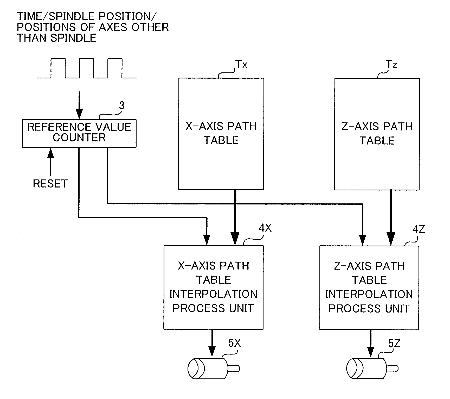
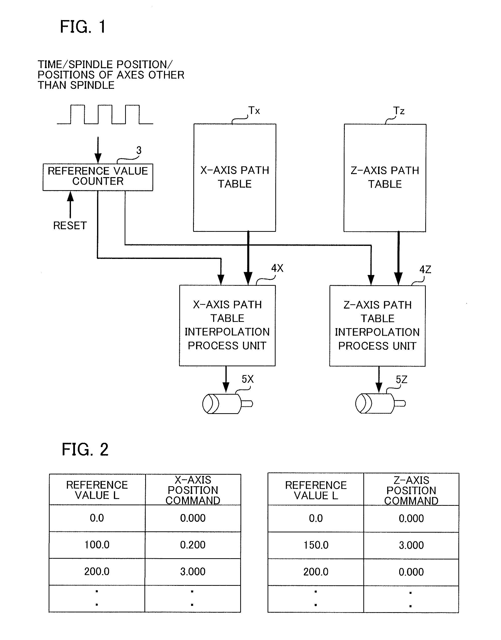
The present invention provides a numerical controller with a smoothing function for a machine tool that corrects tool path data to achieve a smooth finished surface. This eliminates the need for users to manually adjust the path table data and prevents shocks caused by sudden changes in velocity. The correction range is small, and the axes are synchronized with the reference values outside the correction range to maintain synchronization.

Problems solved by technology

In table format data-based operations, when the accuracy of the table format data output by a CAM is poor, the velocity between respective command positions changes greatly, and it may be difficult to process a machining surface smoothly.

Method used


Image

  • Numerical controller for smoothing tool path in operation based on table format data
  • Numerical controller for smoothing tool path in operation based on table format data
  • Numerical controller for smoothing tool path in operation based on table format data

Examples


Embodiment Construction

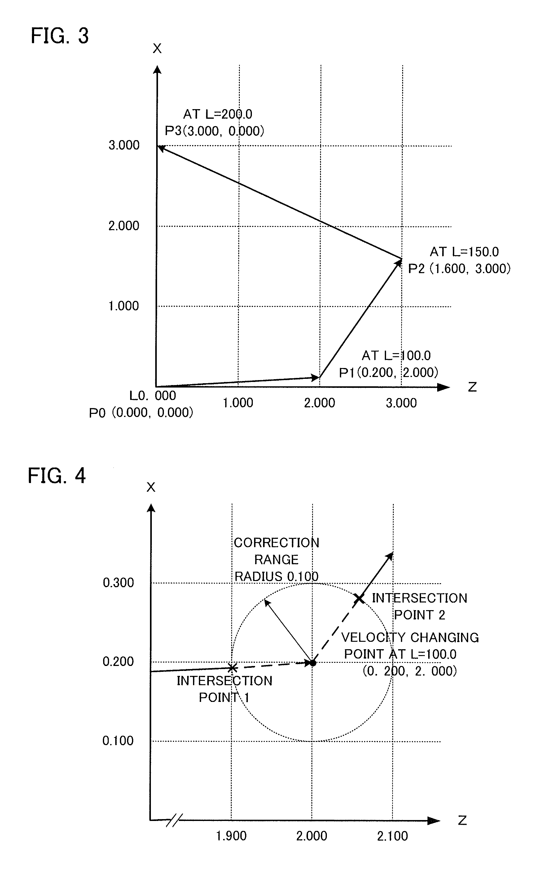
[0033]First, an overview of operation control according to an embodiment of the present invention will be described. In the present embodiment, path tables of all axes associated with a tool path to be synchronized are read in advance in parallel to calculate the tool path, a velocity changing point is detected, and a portion of the tool path within a predetermined range before and after the velocity changing point is corrected. In operations based on table format data, since it is very important to synchronize a reference value with a coordinate value of an axis to be synchronized with the reference value, it is necessary to guarantee that synchronization is maintained after correction. Due to this, a range (correction range) where correction is performed is limited to a predetermined distance from the velocity changing point, and synchronization between the reference value and the coordinate values of respective axes is maintained completely for the other positions where correctio...


PUM


Abstract

Positions to be synchronized with a reference value are stored as command data in table format. Velocity changing points of a tool path designated by the table format data are calculated. Two intersection points between the tool path and a circle or a sphere having a designated radius and centered on the velocity changing point are connected by a smooth curved tool path according to a multidimensional function or the like. In this way, the table format data is corrected.

Description

BACKGROUND OF THE INVENTION[0001]1. Field of the Invention[0002]The present invention relates to a numerical controller for controlling machine tools and various industrial machines, and more particularly, to a numerical controller for controlling a machine tool and the like based on table format data.[0003]2. Description of the Related Art[0004]There is known a numerical control method (so-called electronic cam control) of machine tools, in which a feed axis position and a spindle position synchronized with reference values are stored in a memory in a table form as command data so as to correspond to the reference values rather than commands from respective blocks of a NC program, to control the feed axis position, the spindle position, and the like, based on the table format data stored in the memory. In operations based on table format data, the position of a axis synchronized with a reference value can be controlled accurately even when the speed of advance of the reference valu...

Claims


Application Information

Patent Timeline
IPC IPC(8): G05B19/19
CPCG05B2219/36342G05B19/19
Inventor HARAGUCHI, TAKAHIROTAKEUCHI, YASUSHI
Owner FANUC LTD
Learn More