Reflection-type optical circulator utilizing a lens and birefringent plates

a circulator and lens technology, applied in the field of optical systems, can solve problems such as optical alignment difficulties, and achieve the effect of facilitating the alignment of optical ports, reducing the number of required optical elements and the resultant device siz

Inactive Publication Date: 2005-02-08
II VI DELAWARE INC
View PDF31 Cites 3 Cited by
  • Summary
  • Abstract
  • Description
  • Claims
  • Application Information

AI Technical Summary

Benefits of technology

The present invention provides a reflection-type improved optical circulator. The reflection-type optical circulator includes at least one birefringent plate for receiving at least one signal light ray from a first port; and a mirror optically coupled to the at least one birefringent plate, where the mirror and the at least one birefringent plate causes the at least one signal light ray to be folded back upon itself, where the at least one signal light ray is directed to a second port. The optical circulator in accordance with the present invention is a reflection-type optical circulator, in which the paths of throughgoing light rays are folded back upon themselves. This minimizes the number of required optical elements and the resultant device size by using each optical element two times for each light ray. Furthermore, the reflection-type optical circulator in accordance with the present invention can facilitate the alignment of the optical ports to the remaining optical elements because all ports can be disposed within a tightly constrained geometrical arrangement at only one side of the device.

Problems solved by technology

Such conventional arrangements are bulky and complex and cause difficulties for optical alignment.

Method used


Image

  • Reflection-type optical circulator utilizing a lens and birefringent plates
  • Reflection-type optical circulator utilizing a lens and birefringent plates
  • Reflection-type optical circulator utilizing a lens and birefringent plates

Examples


first embodiment

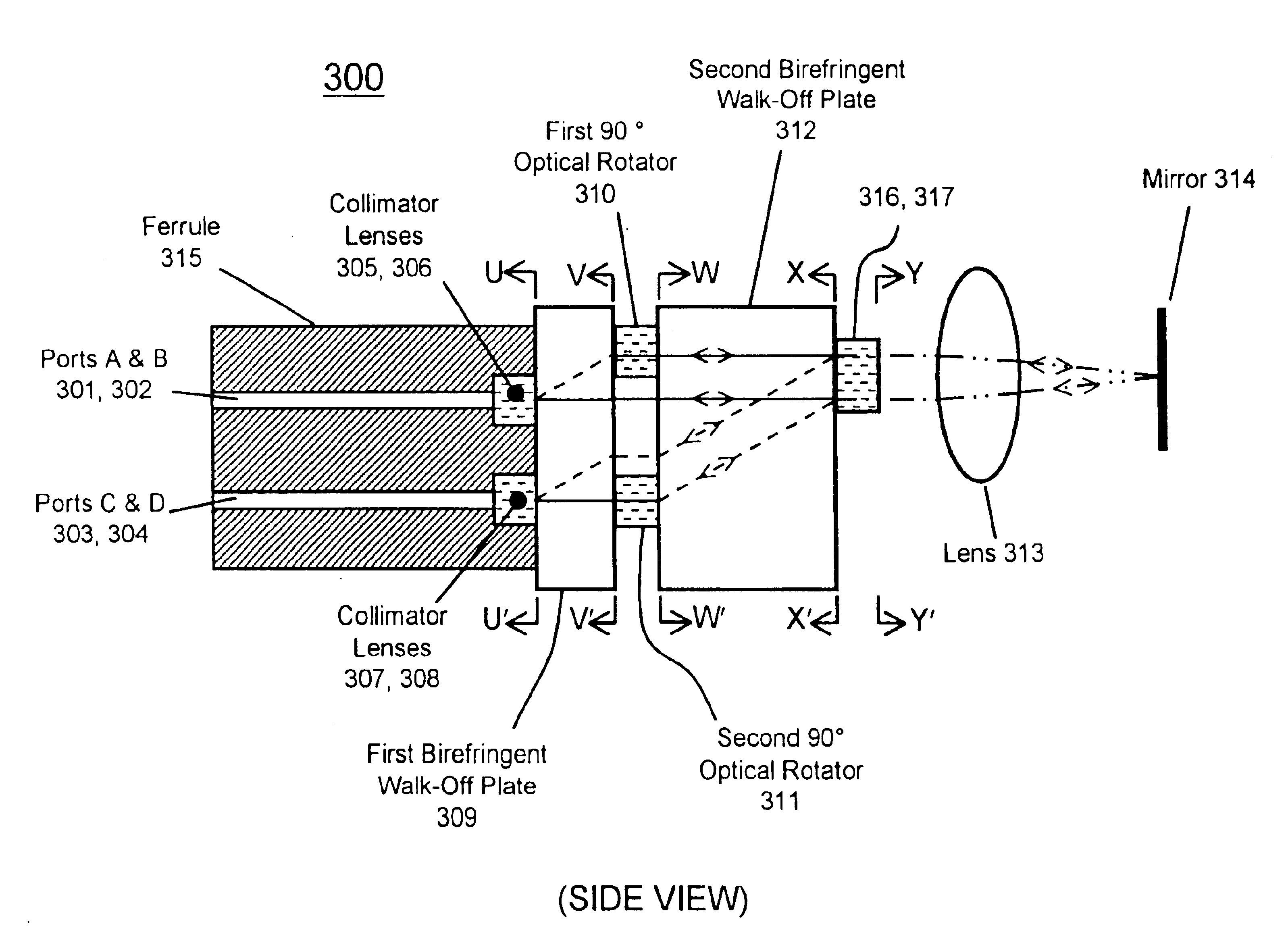
The operation of circulator 300 is now described with reference to FIG. 6. FIG. 6 is a sequence of cross sections through the circulator 300 illustrating the locations and polarization states of port images created by the light of signals and sub-signals propagating therethrough. These cross-sections are all drawn as viewed from the left side of the device 300 of FIG. 3 and are taken at the labeled cross-sectional planes U-U′, V-V′, W-W′, X-X′, and Y-Y′. These cross-sections correspond to locations similarly labeled on FIG. 3. In the cross sections of FIG. 6, the centers of labeled circles denote the positions of port images created by sub-signals propagating through circulator 300 as projected onto the respective cross section. Concentric circles of different sizes indicate overlapping or co-propagating sub-signals. The sizes of these circles in the diagrams of FIG. 6 have no physical significance. Barbs on the circles of FIG. 6 indicate the orientations of polarization planes of t...

second embodiment

Aside from the means of superimposing sub-signal images, other aspects of the operation of the second circulator embodiment, circulator 700, are identical to those already described for circulator 300 and are not described in further detail here. The second embodiment, circulator 700, has the advantage that a birefringent wedge of precise thickness and orientation is not required to superimpose the various sub-signal images. Precise positioning of the various sub-signals in circulator 700 may be accomplished by slight tilt adjustments of the beam-turning reflector 701 and / or the polarization beam splitter 702.

An improved optical circulator has been disclosed. The optical circulator in accordance with the present invention is a reflection-type optical circulator, in which the paths of throughgoing light rays are folded back upon themselves. This minimizes the number of required optical elements and the resultant device size by using each optical element two times for each light ray. ...


PUM


Abstract

The present invention provides a reflection-type improved optical circulator. The reflection-type optical circulator includes at least one birefringent plate for receiving at least one signal light ray from a first port; and a mirror optically coupled to the at least one birefringent plate, where the mirror and the at least one birefringent plate causes the at least one signal light ray to be folded back upon itself, where the at least one signal light ray is directed to a second port. The optical circulator in accordance with the present invention is a reflection-type optical circulator, in which the paths of throughgoing light rays are folded back upon themselves. This minimizes the number of required optical elements and the resultant device size by using each optical element two times for each light ray. Furthermore, the reflection-type optical circulator in accordance with the present invention can facilitate the alignment of the optical ports to the remaining optical elements because all ports can be disposed within a tightly constrained geometrical arrangement at only one side of the device.

Description

FIELD OF THE INVENTIONThe present invention relates to optical systems, and more particularly to circulators in optical systems.BACKGROUND OF THE INVENTIONThe conventional optical circulator is a non-reciprocal multi-port routing and isolation component used in optical communications systems. FIG. 1 illustrates the operation of a generalized conventional four-port optical circulator 100. Light that enters the circulator 100 at port A 102 exits the optical circulator 100 at port B 104. However, light that enters the conventional optical circulator 200 at port B 104 does not travel to port A 102 but instead exits at port C 106. Similarly, light entering the port C 106 exits only at port D 108, and light entering port D 108 exits only at port A 102. In general, given a set of n equivalent optical input / output ports comprising a certain logical sequence within an optical circulator, light inputted to any port is outputted from the logical next port in the sequence and is prevented from ...

Claims


Application Information

Patent Timeline
Patent Type & Authority Patents(United States)
IPC IPC(8): G02B5/30G02B6/26
CPCG02B6/2746G02B5/3083
Inventor CAO, SIMON X. F.
Owner II VI DELAWARE INC
Why Eureka
Try Eureka