Tube-in-plate cooling or heating plate

Active Publication Date: 2005-02-08
LYTRON
View PDF7 Cites 51 Cited by
  • Summary
  • Abstract
  • Description
  • Claims
  • Application Information

AI Technical Summary

Benefits of technology

The invention will be more fully und

Problems solved by technology

As it is generally known, overheating of various types of electronic components may result in their failure or destruction.
The need for effective heat removal techniques in this area is accordingly a basic problem.
However,

Method used


Image

  • Tube-in-plate cooling or heating plate
  • Tube-in-plate cooling or heating plate
  • Tube-in-plate cooling or heating plate

Examples


Example

All disclosures of provisional patent application Ser. No. 60 / 371,879, entitled “TUBE-IN-PLATE COLD PLATE”, filed Apr. 11, 2002, and provisional patent application Ser. No. 60 / 385,406, entitled “TUBE-IN-PLATE COLD PLATE HAVING CARBIDE PLATE”, filed Jun. 3, 2002, are hereby incorporated herein by reference.

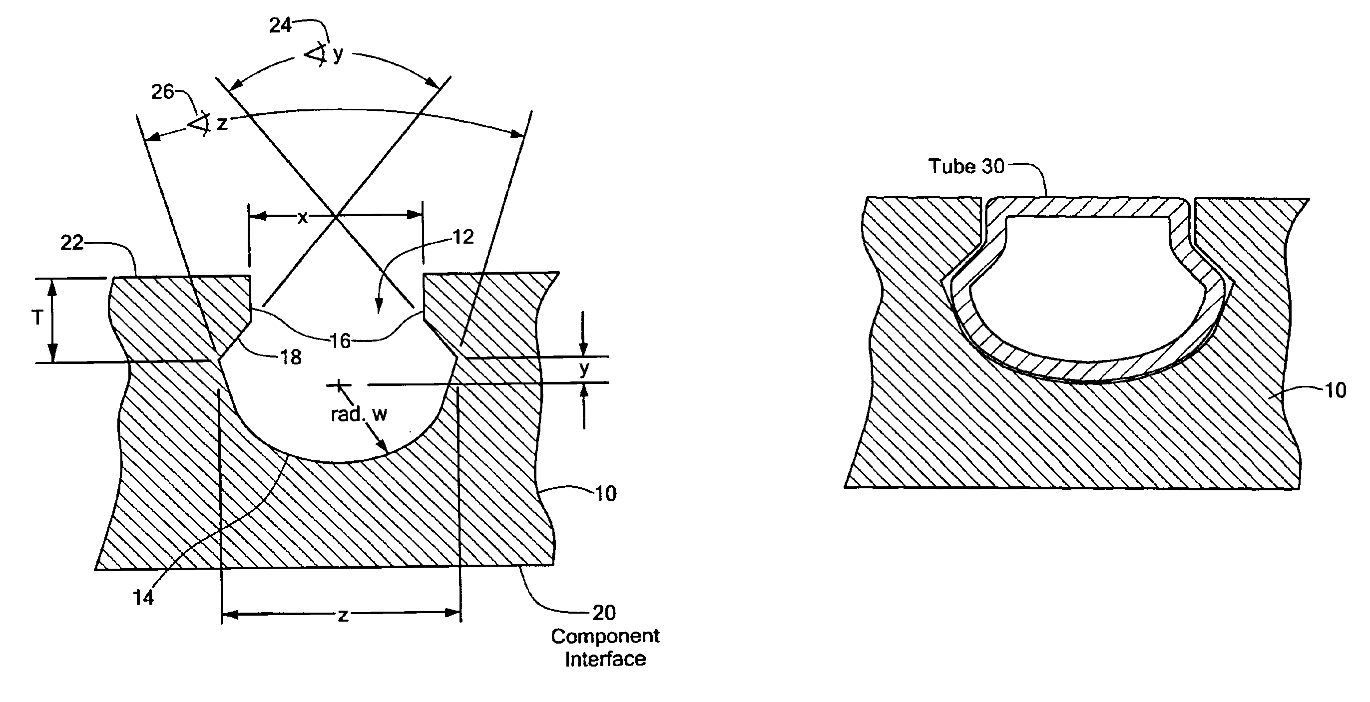
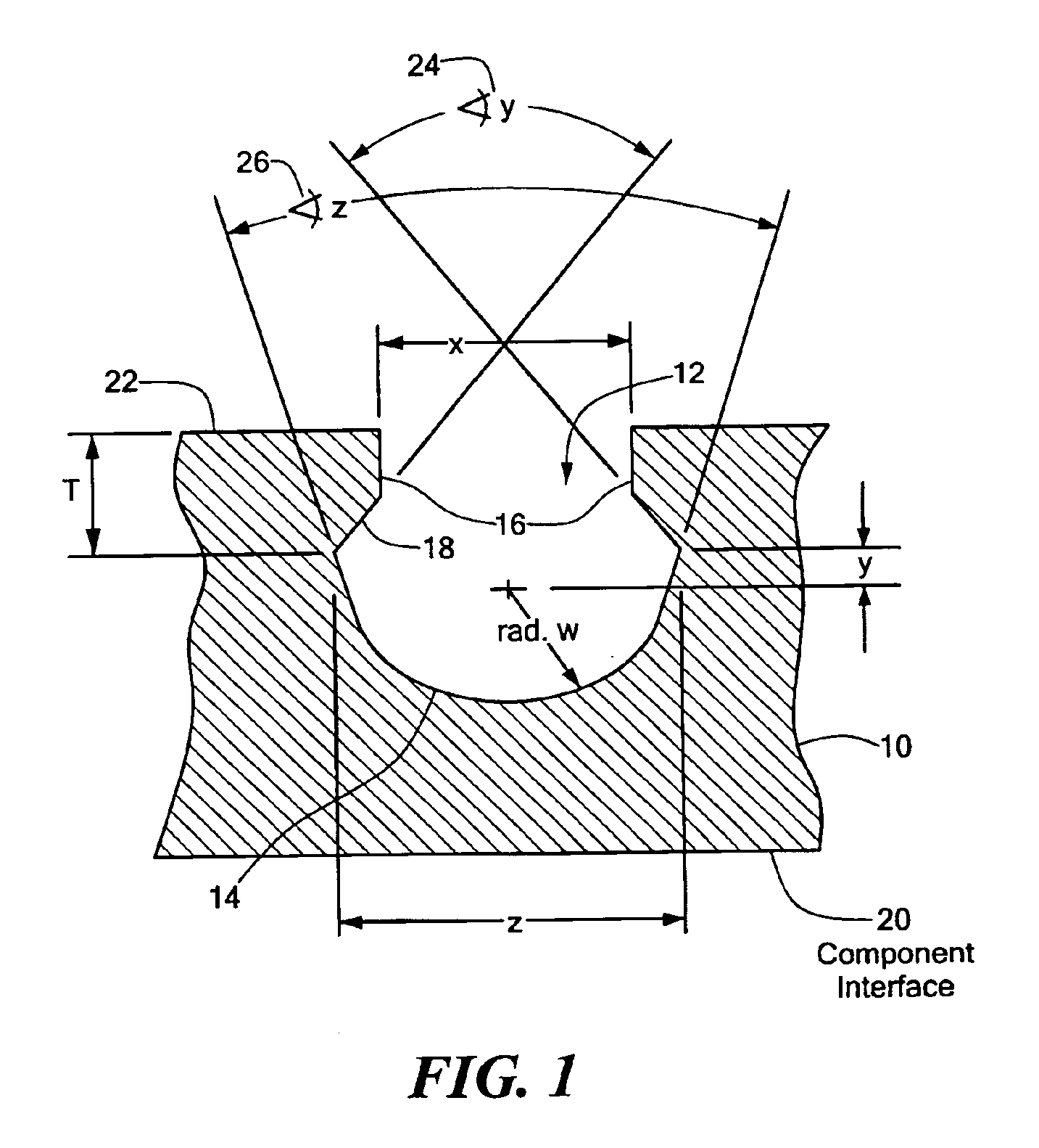
FIG. 1 shows a base plate 10 with a groove 12 for press fitting of a liquid flow tube in accordance with an illustrative embodiment. As shown in FIG. 1, the plate 10 includes the groove 12, the groove 12 adapted to receive a tube such that the tube is held within the groove after the tube is press fitted into the groove 12. In the illustrative embodiment of FIG. 1, the groove 12 is defined by a first surface 14 at the bottom of the groove 12. The surface 14 in FIG. 1 is shown for purposes of illustration as including a curve. The illustrative groove 12 of FIG. 1 is shown further defined by a pair of side surfaces 16 forming a channel into the groove 12 through a top side of the pla...


PUM

PropertyMeasurementUnit
Angleaaaaaaaaaa
Heataaaaaaaaaa
Mechanical forceaaaaaaaaaa

Abstract

A low thermal resistance, low cost cooling or heating system and method of constructing the disclosed cooling system. The system may be formed by pressing a tube into a groove in a plate without the use of interface materials or epoxy. The disclosed system includes a plate having a channel adapted to receive a tube, such that the channel holds the tube in place after the tube is press fitted into the channel, thus forming an effective cooling or heating system without the need for addition of epoxy or interface material between the tube and the plate. One or more electronic components to be cooled or heated may be attached to both sides of the disclosed cooling system with equivalent cooling effectiveness. Operation of the disclosed system involves flowing an appropriate fluid through the tube that has been press fitted into the plate.

Description

STATEMENT REGARDING FEDERALLY SPONSORED RESEARCH OR DEVELOPMENTN / ABACKGROUND OF THE INVENTIONThe present invention relates generally to a cooling or heating apparatus and more specifically to a design for a tube-in-plate cold plate.As it is generally known, overheating of various types of electronic components may result in their failure or destruction. The need for effective heat removal techniques in this area is accordingly a basic problem. Various types of systems have been designed to cool electronic components in order to increase the MTBF (Mean Time Between Failure) of those components. In some existing systems, fluid has been passed through cold plates or heat sinks in order to transfer heat away from devices or components to be cooled. Such existing systems have used interface materials or epoxy to fill the air gap between the tube and the plate, in order to lower thermal resistance and increase the amount of heat transferred away from the component. However, the use of int...

Claims


Application Information

Patent Timeline
IPC IPC(8): H01L23/473H01L23/34H05K7/20
CPCH01L23/473H05K7/20927Y10T29/4935H01L2924/0002H01L2924/00
Inventor FICHERA, BENJAMIN J.FRANCHINA, JOHNAKSELBAND, BORISMOISIDIS, THEODORVOORHES, DAVID W.
Owner LYTRON
Why Eureka
Try Eureka