
Method and apparatus for controlling a multi-source heating system

a multi-source heating and control method technology, applied in lighting and heating apparatus, heating types, instruments, etc., can solve the problems of the heat pump's tendency to degrade, and achieve the effect of reducing the cost of operation, and increasing the efficiency of the system

Inactive Publication Date: 2005-04-05
ADEMCO INC
View PDF19 Cites 110 Cited by
  • Summary
  • Abstract
  • Description
  • Claims
  • Application Information

AI Technical Summary

Benefits of technology

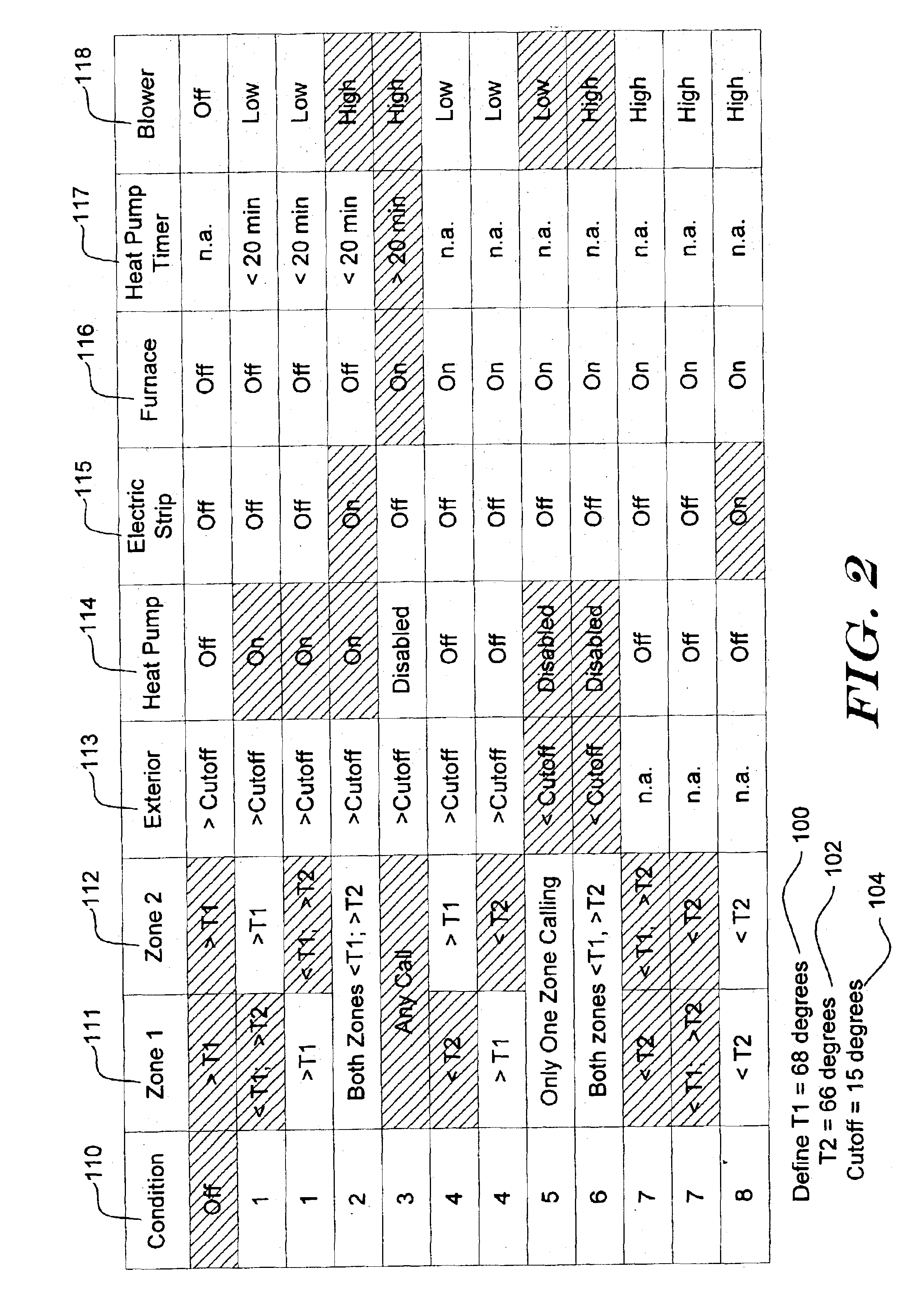
Rather than simply deactivating the heat pump when the outside air temperature reaches a predetermined temperature threshold value, the present invention contemplates continuing to use the heat pump to satisfy heat calls that correspond to less than the entire heated space. As noted above, the heating capacity of a heat pump may tend to degrade as the outside air temperature decreases. However, even at a reduced capacity, the heat pump may still have sufficient heating capacity to heat less than the entire space or enclosure. Thus, in a multi-zone system for example, the heat pump source may be efficiently used when less than all of the zones are calling for heat.
In accordance therewith, it is contemplated that the controller of the present invention may be adapted to determine whether the heat pump source is capable of providing sufficient heat to satisfy the expected heating load of the zone(s) that are currently calling for heat. If so, the controller may activate the heat pump source to satisfy the call for heat. If not, the controller may activate an auxiliary heat source, sometimes in combination with the heat pump, to satisfy the call for heat. This may provide a more efficient system.

Problems solved by technology

As noted above, the heating capacity of a heat pump may tend to degrade as the outside air temperature decreases.
However, even at a reduced capacity, the heat pump may still have sufficient heating capacity to heat less than the entire space or enclosure.

Method used


Image

  • Method and apparatus for controlling a multi-source heating system
  • Method and apparatus for controlling a multi-source heating system
  • Method and apparatus for controlling a multi-source heating system

Examples


Embodiment Construction

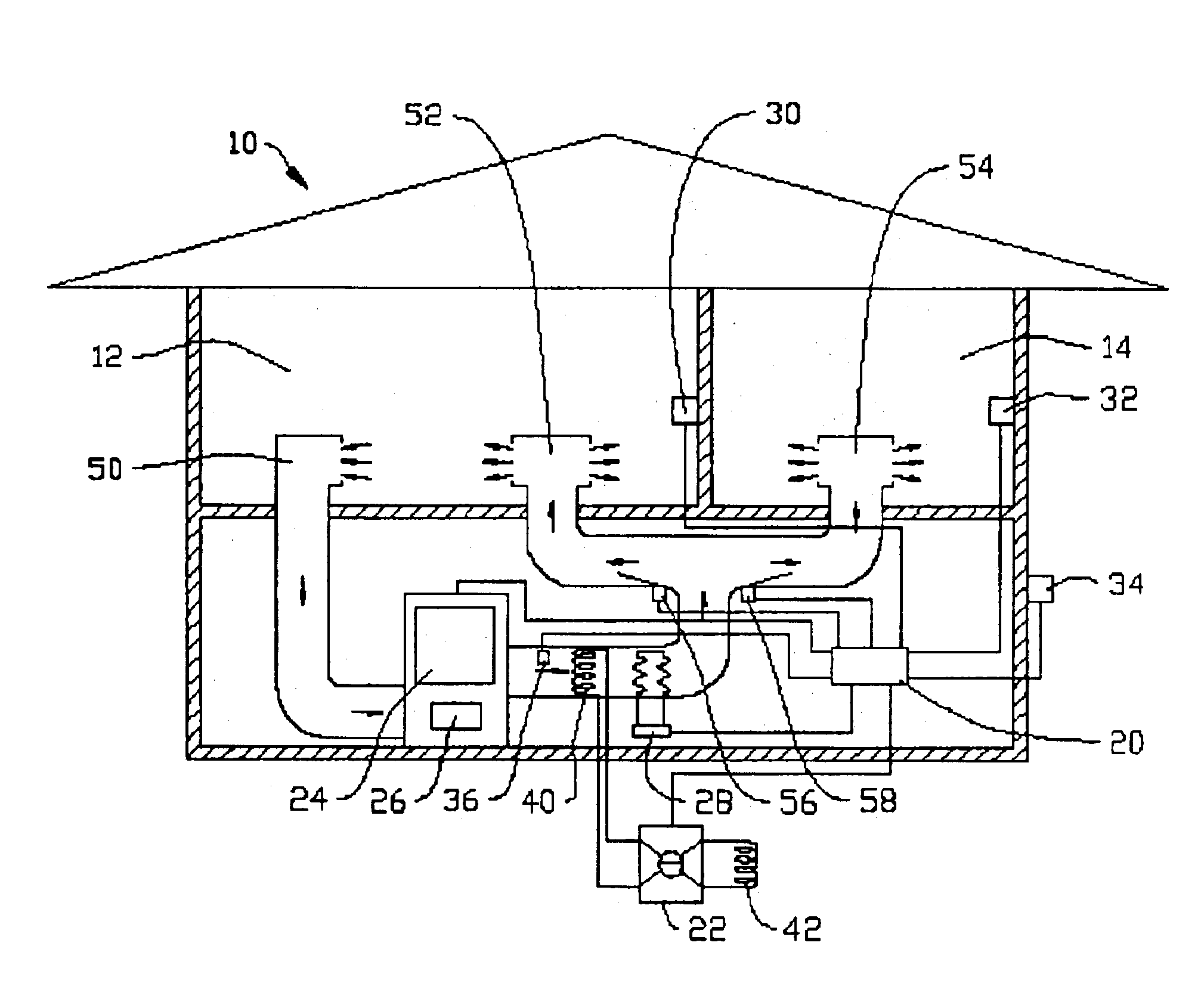
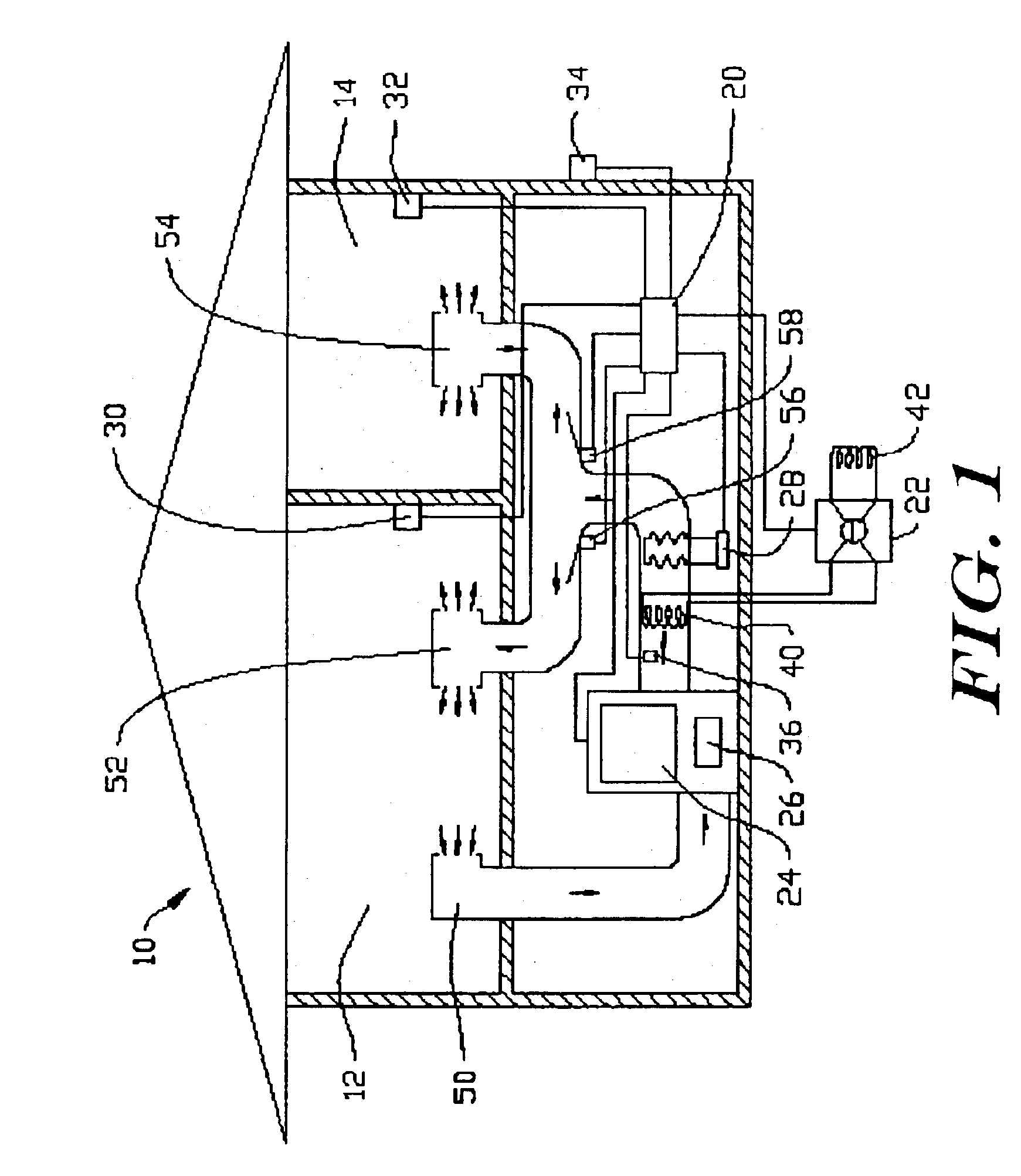
FIG. 1 shows a highly diagrammatic structure adapted for environmental control by a zoned multi-source heating system. While the present invention is not limited to multi-zoned systems, a multi-zoned system is used for illustration. The system shown in FIG. 1 is used to control the temperature in an enclosure 10 in which a first zone 12 and a second zone 14 have been defined. The illustrative system includes a controller 20 which controls a heat pump 22, a furnace 24, and a blower 26 along with a heat strip 28 which may be included as a third heat source. Though a furnace 24 is shown as an auxiliary heat source, any suitable heat source may be included as an auxiliary heat source. Some suitable auxiliary heat sources include natural gas, propane, fuel oil or other fossil fuel furnaces, wood, pellet or other burning sources, boilers, or a variety of electric sources including, for example, electric heat strips. The auxiliary heat source may also be one or more auxiliary stages of a m...


PUM


Abstract

The present invention is directed at methods and apparatus for controlling multi-source heating systems. The multi-source heating systems of the present invention may include two or more heat sources such as a heat pump, a furnace, an electric heating strip, or any other suitable heat source. An illustrative system includes a multi-zone, multi-source heating system. The illustrative system may determine which of the multiple sources to use depending on a number of factors. Some illustrative factors include information about zones calling for heat, external environment information, and information about the heat sources. One of the heat sources may be, for example, a heat pump, and a determination of whether to activate the heat pump may include determining the current heating capacity of the heat pump and comparing the heating capacity to the amount of heat needed to satisfy the current heat calls. Methods for determining which of at least two heat sources to use are also provided. Additional embodiments include methods for controlling multiple-source heating systems, and systems for providing heat with multiple sources.

Description

BACKGROUNDThe invention relates generally to heating systems, and more specifically, to multi-source heating systems.A relatively recent innovation in heating systems has been the introduction of multi-source heating systems. Several such systems use a heat pump as a primary heating source. Auxiliary sources are then provided to add heat during times when the heat pump does not function efficiently. Some typical auxiliary sources include fossil fuel furnaces (i.e. fuel oil, propane or natural gas furnaces, for example), electric heating strips, as well as other heat sources.As is known, heat pumps may be used to heat an interior space by transporting heat from an exterior environment to an interior space. Air-to-air heat pumps operate to transport heat contained in outside air to warm the interior space. Water-to-air heat pumps operate to transport heat from water (for example groundwater or a nearby pond or other water source) to warm an interior space. Ground source heat pumps ope...

Claims


Application Information

Patent Timeline
IPC IPC(8): F24D12/00F24D12/02F24F3/00G05D23/19H05B1/02
CPCF24D12/02F24F3/001G05D23/1935H05B1/028F24D2200/04F24D2200/08Y02B30/14F24D2200/12Y02B30/00
Inventor READIO, PHILIP O.SCHWENDINGER, PAUL G.HULSE, ANDREW J.
Owner ADEMCO INC
Learn More