Fixing device and image forming apparatus

a fixing device and image technology, applied in the direction of electrographic process, electric/magnetic/electromagnetic heating, instruments, etc., can solve the problems of reducing the lifetime of the fixing device, increasing the temperature at the end, and unable to handle a limited number of definite shape sizes

Active Publication Date: 2009-06-11
RICOH KK
View PDF19 Cites 110 Cited by
  • Summary
  • Abstract
  • Description
  • Claims
  • Application Information

AI Technical Summary

Benefits of technology

[0012]Such a new and noble fixing device includes a heat applying system having an exciting coil that creates a magnetic flux for generating induction heat in a heat generation layer provided in a fixing roller. Plural demagnetizing coils are stacked in plural layers partially overlying the exciting coil to cancel the magnetic flux at one end of the fixing roller. The plural demagnetizing coils partially overlap each other.

Problems solved by technology

However, when a smaller size of a sheet than a prescribed heat application width is repeatedly fed though a fixing device of a low calorie type, since a sheet passage section releases the calorie to the sheet while a non-sheet passage section does not, temperature increases at the ends thereof.
As a result, an image deteriorates or a lifetime of the fixing device decreases.
However, the technology of the Japanese Patent Application Laid Open No. 2001-060490 can only handle a limited number of definite shape sizes.
As a result, a fixing performance is defective.
Otherwise, brilliance becomes uneven for the same reason resulting in creating an uncomfortable image.
That is, since a heat conducting cross section reduces in the fixing device and a heat flattening performance deteriorates in a direction in parallel to an axis of a rotation member, the above-mentioned problem becomes prominent.
Further, since the temperature increases at both ends, an elastic member and a protecting film and the like arranged on the heat-applying roller can be damaged.

Method used


Image

  • Fixing device and image forming apparatus
  • Fixing device and image forming apparatus
  • Fixing device and image forming apparatus

Examples


first embodiment

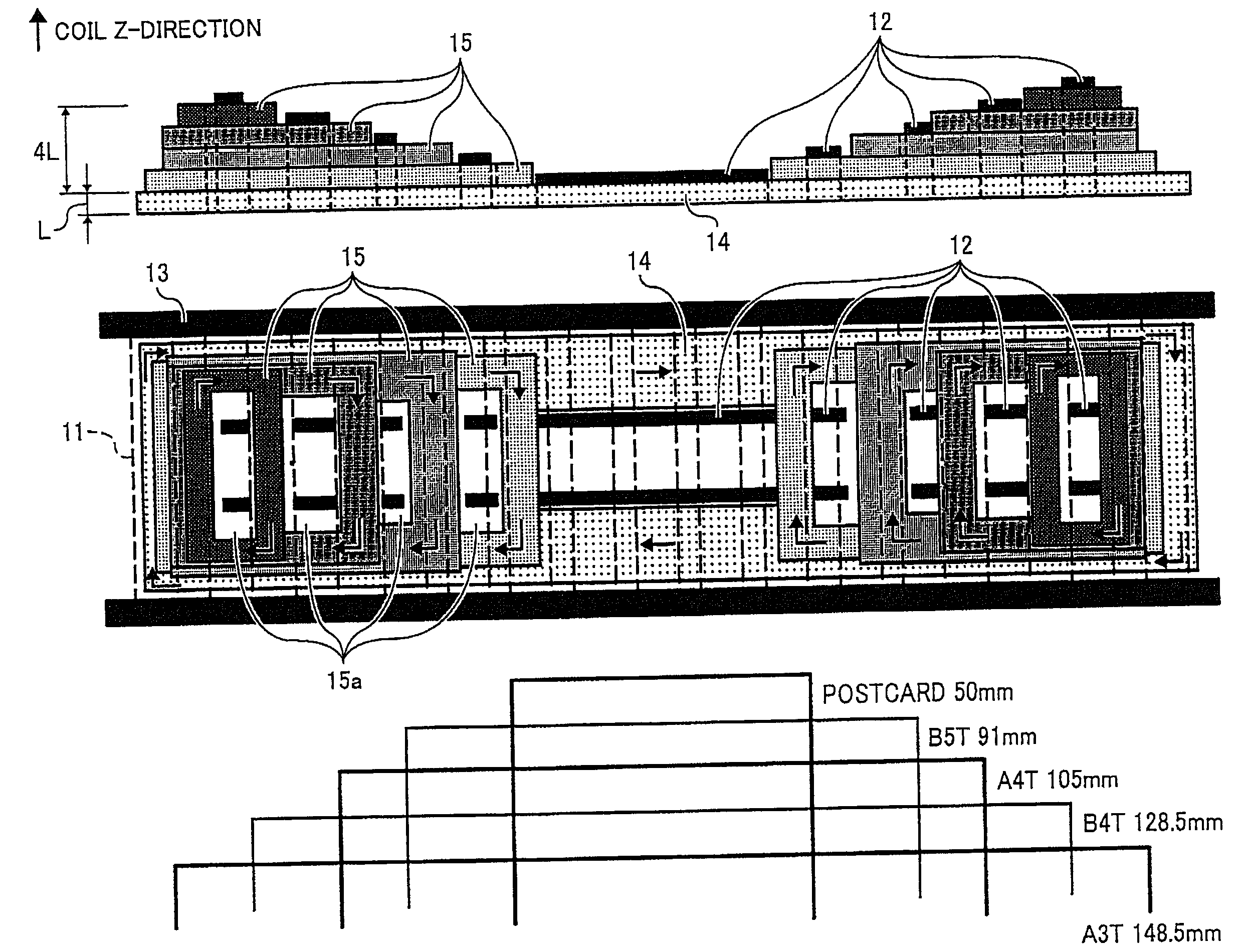
[0036]Now, the first embodiment is described with reference to FIG. 4. As shown, plural loops arranged on the exciting coil 14 typically illustrate demagnetizing coils 15. The uppermost chart illustrates a condition of overlapping of the exciting and demagnetizing coils 14 and 15 in a direction Z, wherein the arch cores 11 are omitted. The lower chart illustrates a plan view of such overlapping. The arch cores 11 are shown by dotted lines in the plan view. As shown, the demagnetizing coils 15 have a different size from the other, and are arranged on the exciting coil 14 in accordance with a heat application width while forming more than two steps in the direction Z. The demagnetizing coils 15 a realigned at one side endbeing partially overlapped on their sides with each other.

[0037]However, each of inner loop spaces 15a formed inside the demagnetizing coils 15 and a right or left side of the other demagnetizing coil 15 are arranged avoiding overlap with each other. Because, when the...

second embodiment

[0041]Now, the present invention is described with reference to FIG. 5. As shown, a plurality of magnetic coils 15 having substantially the same size are arranged stepwise such that lop spaces 15a formed in the magnetic coils 15 are not interfered by the other magnetic coil 15. For this purpose, the demagnetizing coils 15 are downsized in accordance with the size of the sheet and are partially overlapped with each other in the direction Z on a left or right side thereof. Thus, a coil unit of the magnetic coils 15 and the exciting coil 14 does not grow mammoth in the direction Z (i.e., perpendicular to the demagnetizing coil 15 winding surface).

[0042]Further, it is effective to arrange the center cores 12 in the inner loop spaces, because demagnetization of the exciting magnetization flux is more effective. Although the center cores 12 are largely omitted, the heat distribution can be optimized if the demagnetizing coil are preferably shaped and sized.

[0043]Now, the third embodiment ...

third embodiment

[0045]Then, plural demagnetizing coils 15 having substantially the same size are staggered on an exciting coil 14 being partially overlapped with each other on right or left sided thereof in the direction z, while avoiding the inner loop spaces 15a of the demagnetizing coils 15 from being interfered by the other demagnetizing coils 15.

[0046]Specifically, at least three layers are partially overlapped each other while at least two of them are arranged in the direction Z at substantially the same distance. Specifically, the demagnetizing coils 15 are stacked partially overlapping each other in two stages as shown in FIG. 6.

[0047]Thus, mammoth growing of the heat-applying device 10 can be suppressed. Although the center cores 12 are omitted from sections in which the demagnetizing and exciting coils 15 and 14 overlap each other, since the demagnetizing coils 15 are stacked being partially overlapped in the direction z, the amount of omission of the center cores 12 can be suppressed to...


PUM


Abstract

A fixing device includes a heat applying system having an exciting coil that creates a magnetic flux for generating induction heat in a heat generation layer provided in a fixing roller. Plural demagnetizing coils are stacked in plural layers partially overlying the exciting coil to cancel the magnetic flux at one end of the fixing roller. The plural demagnetizing coils partially overlap each other.

Description

CROSS REFERENCE TO RELATED APPLICATION[0001]This application claims priority under 35 USC § 119 to Japanese Patent Application No. 2007-320012, filed on Dec. 11, 2007, the entire contents of which are herein incorporated by reference.BACKGROUND OF THE INVENTION[0002]1. Field of the Invention[0003]The present invention relates to a fixing device having a heat-applying device of an electromagnetic induction heat applying system, and in particular, to a fixing device and an image formation apparatus employing the fixing device.[0004]2. Discussion of the Background Art[0005]In an image forming apparatus, such as a copier, a printer, a facsimile, a duplicator, a multifunction machine of those, etc., an image is created by transferring a toner image carried on a latent image carrier onto a recordation medium like a sheet. The toner image is fixed onto the recordation member due to an operation of melting and a penetration behavior of the toner subjected to heat and pressure when the toner...

Claims


Application Information

Patent Timeline
Patent Type & Authority Applications(United States)
IPC IPC(8): G03G15/20H05B6/02
CPCG03G15/2042
Inventor SEO, HIROSHIHASE, TAKAMASA
Owner RICOH KK
Why Eureka
Try Eureka