Solid state light fixture with cooling system with heat rejection management

a technology of heat rejection management and light fixture, which is applied in the field of solid-state light fixture with heat rejection management, can solve the problems of increasing the total cost of cooling the building, difficulty in adequate heat rejection, and waste of energy from lighting systems and other components, so as to reduce the operating temperature of the light source and/or power circuit, reduce the contribution of heat load from the fixture, and reduce the contribution of heat load

Active Publication Date: 2014-02-18
MUSCO
View PDF77 Cites 112 Cited by
  • Summary
  • Abstract
  • Description
  • Claims
  • Application Information

AI Technical Summary

Benefits of technology

[0015]Potential benefits of such heat management include not only collectable and beneficial use of heat. Potential benefits also include but are not limited to allowing increased operating power to the light source which can produce more light output, increased life of the light source, possible reduction of the number of light sources needed for a given lighting application, possible reduction in size, type, or function of other heat management apparatus or methods (e.g. heat sinks), possible reduction in cost or complexity of components, increase in service life, and reduction in maintenance and replacement costs, among others.
[0017]Some embodiments include a method of cooling a lighting fixture and transferring heat from a fixture to a location more or less separated from the fixture. Some embodiments include a method of cooling a lighting fixture and reducing the heat load contribution from the fixture for an interior space that is conditioned (e.g. air conditioned, HVAC conditioned, or the like). Some embodiments include a method of cooling a lighting fixture, reducing the heat load contribution from the fixture for an interior space that is conditioned, and using the heat for useful purposes, such as e.g. heating conditioned space, conversion into other forms of energy, or recycling by heating water, etc.
[0018]Some embodiments pump fluid through the fixture to reduce the operating temperature of the light source and / or power circuits. Some embodiments pump air through the fixture to reduce the operating temperature of the light source and / or power circuits. In some embodiments, the heated air can be optionally exhausted outside the building when the air-conditioning is operating. In some embodiments, the heated air can be optionally exhausted inside the building if the extra heat is desirable. Some embodiments pump liquid through the fixture to reduce the operating temperature of the light source and / or power components.
[0019]Also envisioned are systems, methods, and apparatus which provide many benefits for solid-state lighting. These benefits can include at least some of the following: cooling a solid-state lighting fixture thereby allowing it to operate at higher wattage, reducing the size of the fixture and / or number of LEDs or other solid-state source(s), increasing lumen output; and providing benefits to an associated building or structure by managing heat generated by lighting. These benefits may be realized with lighting used in conditioned spaces by reducing the heat contribution to conditioned space; and / or if separate from HVAC system, can reduce load on cooling system due to what might be called a “concentration advantage” of more efficient transfer due to higher heat density in the envisioned enclosures, and what might be called an “isolation advantage” due to reduced conduction to associated structures; heat may be directed to a desired location such as outdoors, indoors for heating, indoors for conversion / recycling (e.g. through a heat exchanger to heat water, a thermocouple / thermopile, or peltier effect devices.
[0024]Due to the concentration of heat on the back side of the solid-state light source assembly, it is relatively easy to isolate waste heat from conditioned space. The fact that little or no IR or UV light is emitted from most solid-state lights makes them better for locations for which light in the non-visible spectrum is unwanted or harmful. Since heat is drawn directly away from the light source and not from the entire fixture housing, it does not require transfer of air through the face of the fixture housing to remove heat. Therefore, the lighting system can be a sealed system that draws air from a remote space, other than the enclosed space the fixtures might be in, thus providing benefits for any enclosure or building that requires isolation of air, control of dust, etc.

Problems solved by technology

Consequently, heat from the light fixtures and other components can increase the total cost to cool the building.
In addition to being expensive, the energy rejected from lighting systems and other components is usually wasted.
In these types of locations, adequate heat rejection can be difficult especially when a collection of solid-state electronics is highly concentrated.
Solid-state sports lights on high poles are an example of a situation in which providing adequate ambient heat sinking capability can be difficult due to the given the requirements for construction many feet in the air.
This could lead to inadequate heat sinking capability or performance constraints, and potentially damage or premature failure of lighting or other electrical / electronic components.

Method used


Image

  • Solid state light fixture with cooling system with heat rejection management
  • Solid state light fixture with cooling system with heat rejection management
  • Solid state light fixture with cooling system with heat rejection management

Examples


embodiments

Overview

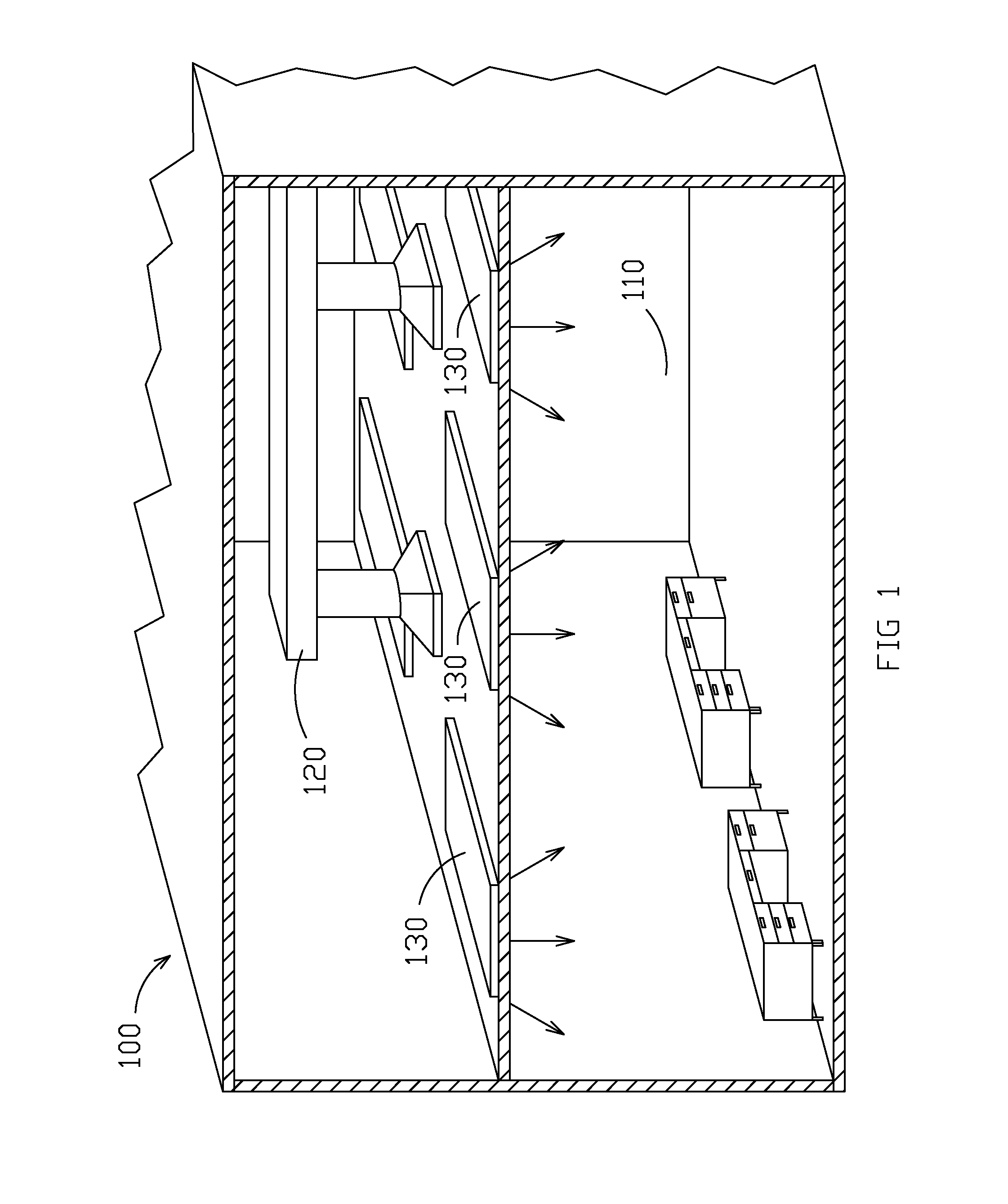
[0077]FIG. 1 illustrates an example of an operating environment 100 in which some embodiments of the present invention may be utilized. Environment 100 shows a space or room 110 that is interior to a building that is temperature controlled. As shown in FIG. 1, the building has a heating ventilation and air conditioning (HVAC) unit and HVAC ductwork 120 installed throughout the building structure. (Alternatively, environment 100 could use a high velocity mini-duct system such as provided by Unico, Inc. (7401 Alabama Ave., St. Louis, Mo. 63111-9906 www.unicosystem.com) instead of conventional HVAC ductwork.) Lighting fixtures 130 provide light to room 110. In addition to light, most light fixtures produce some heat from the light source or the electrical system that provides power to the light fixture.

specific embodiments

Primary Embodiment

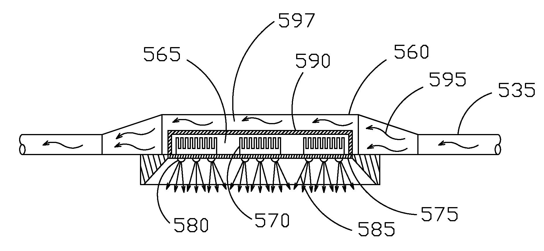
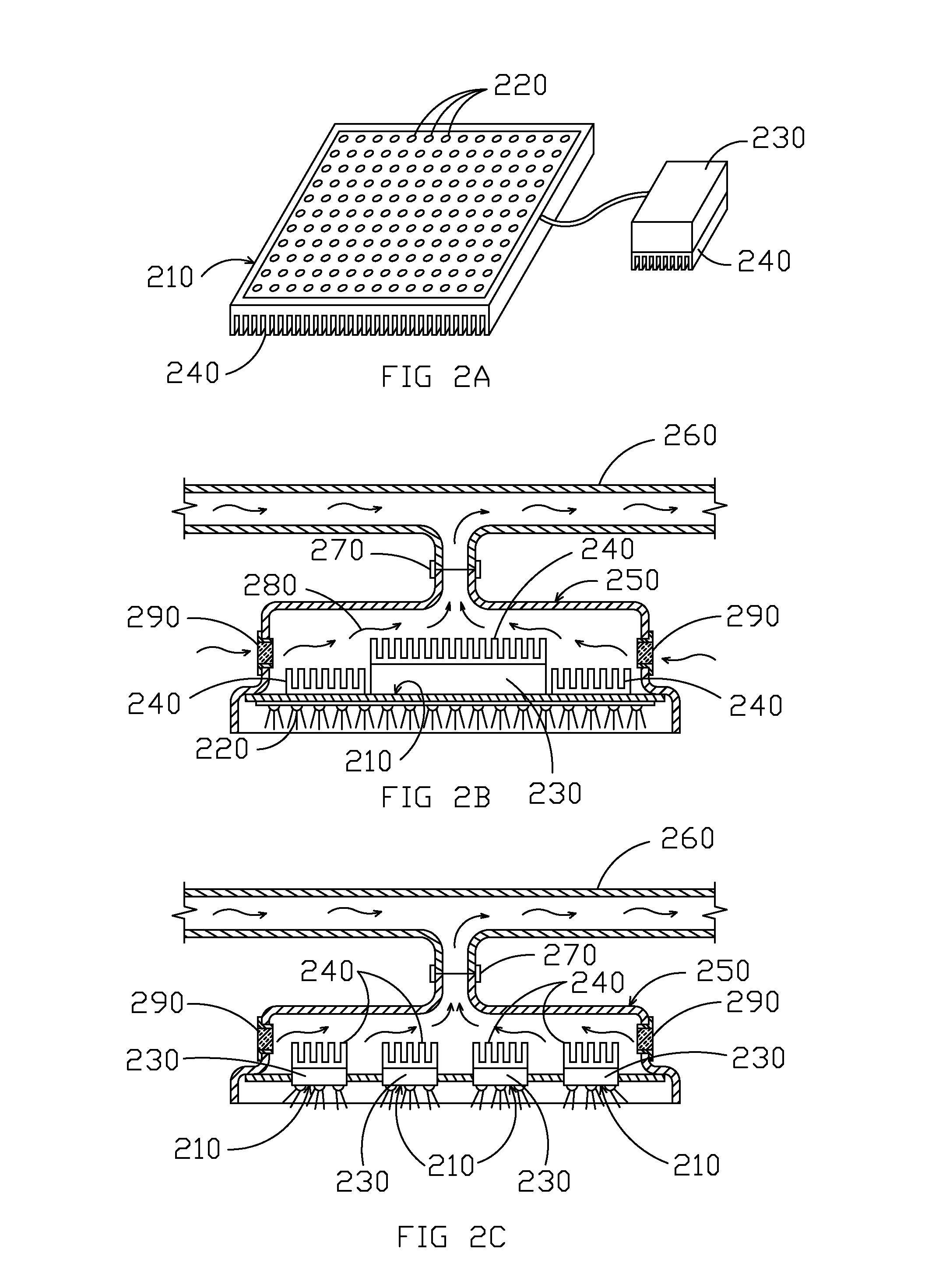
[0078]FIGS. 2A-2C illustrate various views of an example of a solid-state light source with power electronics, an enclosure, and a fluid conduit that may be used in accordance with some embodiments of the present invention. FIG. 2A is a perspective view of LED fixture 210 with an array of LED lights 220 that are powered by power electronics 230. Both LED lights 220 and power electronics 230 can use heat sinks 240 to dissipate heat. Power electronics 230 may be mounted directly on, in close proximity to, or remotely from fixture 210. LED lights 220 can be any type of LED or solid-state light.

[0079]Some embodiments of the present invention use solid-state lighting sources for interior applications. Since solid-state lighting sources generally have a “light side” which can be visible in the living space and which does not ordinarily need to be cooled, and since the “heat side” and the driving electronics do not need to be visible, heat is generally dissipated away fro...

first additional embodiment

[0085]FIGS. 3A-3B illustrate examples of reflective lighting enclosures that may be used in some embodiments of the present invention. FIG. 3A is a cross-sectional view of a first side of lighting enclosure 310 while FIG. 3B is a cross-sectional view of a second side of lighting enclosure 310. As shown in FIGS. 3A-3B, lighting enclosure 310 includes an array of LEDs 320 pointed toward a reflective surface 330 on the inside of lighting enclosure 310. The light 370 (FIG. 3B) emitted from LEDs 320 is reflected from reflective surface 330 toward the target area through transparent plates or covers 380. Examples of reflective materials that can be used in some embodiments of the present invention include, but are not limited to, various surfaces of metal and / or plastic that can be embossed, patterned, and / or otherwise configured for light spread or diffusion. In some embodiments, surfaces of the reflective material can be matte, burnished, semi-specular, specular, etc. Other examples inc...


PUM


Abstract

Systems and methods for solid-state light source heat management are provided. A solid-state light source, e.g. having one or more LEDs, can be mounted within an enclosure. In some embodiments, a heat sink associated with semiconductor material and / or power electronics can be placed on a separate side of the enclosure that is thermally insulated or separated from the state-light source. The enclosure can include a first side or portion that allows light from the solid-state-light source (e.g., LEDs) to pass through to a target area. A fluid transfer conduit may be connected to the second side or portion of the enclosure for passing a fluid (e.g., air, water, coolant, etc.) across the heat sink to transport heat generated by the power electronics and / or semiconductor material away. The heated fluid can then be routed to, as examples, an HVAC system, a vent, water heating systems, heat exchanger systems, and / or storage systems (e.g., batteries).

Description

CROSS-REFERENCE TO RELATED APPLICATIONS[0001]This application claims priority under 35 U.S.C. §119 of provisional U.S. Patent Application No. 61 / 120,251, filed on Dec. 5, 2008, which is hereby incorporated by reference in its entirety for all purposes.COPYRIGHT NOTICE[0002]Contained herein is material that is subject to copyright protection. The copyright owner has no objection to the facsimile reproduction of the patent disclosure by any person as it appears in the Patent and Trademark Office patent files or records, but otherwise reserves all rights to the copyright whatsoever. Copyright© 2008-2009 Musco Sports Lighting, Inc.TECHNICAL FIELD[0003]Some embodiments of the present invention generally relate to heat management systems. More specifically, some embodiments of the present invention relate to heat rejection management in LED and other solid-state lighting fixtures and devices.BACKGROUND[0004]The functional source of heat from an LED is primarily from what will be called th...

Claims


Application Information

Patent Timeline
Patent Type & Authority Patents(United States)
IPC IPC(8): F21V29/00G06F19/00
CPCG06F19/705G06F19/709F21Y2105/001F24F3/056F24F13/078F21Y2101/02F21W2131/10F24F1/00F21V33/006F21V29/60F21V33/0092F21Y2105/10F21Y2115/10G16C20/40
Inventor GORDIN, MYRONCROOKHAM, JOE P.
Owner MUSCO
Why Eureka
Try Eureka