Systems, apparatus and methods for optimizing the rapid pyrolysis of biomass

a biomass and pyrolysis technology, applied in the direction of charging devices, oven incrustation prevention/removal, products, etc., can solve the problems of nuclear power raising the specter of ecological damage, emission of excessive amounts of carbon dioxide into the atmosphere, and substantial environmental problems in the united states, so as to prolong the shelf life, increase the viscosity of the pyrolysis oil, and increase the effect of the viscosity

Active Publication Date: 2017-05-30
AMERICAN BIO ENERGY CONVERTING
View PDF29 Cites 4 Cited by
  • Summary
  • Abstract
  • Description
  • Claims
  • Application Information

AI Technical Summary

Benefits of technology

[0014]One end of the combustion chamber is in communication with a proximate end of a concentric pyrolysis chamber. In embodiments including multiple pyrolysis chambers, an opposite end of the innermost pyrolysis chamber is also in communication with a proximate end of a next-innermost pyrolysis chamber. An opposite end of the next-innermost pyrolysis chamber is, in turn, in communication with a proximate end of a successive pyrolysis chamber, and so on for each successive pyrolysis chamber. In this way, a directed, generally-deoxygenated, heated gas stream flowing from the combustion chamber enters each pyrolysis chamber sequentially. The heated gas stream reverses direction at each junction of chambers such that the stream flows in a first direction through one chamber, and then flows in a second direction generally opposite to the first direction through an adjacent chamber. Each pair of adjacent chambers shares a common wall that separates the gas in each chamber while still conducting heat. For example, the combustion chamber and the inner pyrolysis chamber share a common wall. In addition to heat radiating from the heated gas stream passing through the chambers, each common wall of the pyrolysis unit also conducts heat from one chamber to the next. At the designed temperature of the combustion exhaust, the wall of the combustion chamber will also provide significant radiant heat transfer to the biomass flowing through the first pyrolysis chamber, thereby increasing the rate of heat transfer to the biomass.
[0017]In some embodiments, a cyclone separator is used to separate entrained char from the exhaust. In some embodiments a biomass feed bin is used for introduction of biomass into the pyrolysis unit. In some embodiments, NCG separated from its pyrolysis oil vapor and char is passed through the biomass feed bin whereupon the biomass acts as a filter, cleaning remaining entrained matter from the exhaust. Char separated from the exhaust can be introduced back into the pyrolysis unit to aid in producing the generally-deoxygenated heated gas stream. In some embodiments, NCG is used as the entraining gas in addition to the combustion gas. In yet another embodiment, the exhaust from a gas turbine is used as a heat source to promote an efficient fast pyrolysis.
[0019]The HGF system addresses a problem of char being entrained with the pyrolysis oil vapors following removal of the larger char particles by the cyclone filter. It is known that oil produced via pyrolysis that contains char is not desired, as the char continues to react with the pyrolysis oil forming longer chain molecules and a general increase in the viscosity of the pyrolysis oil. Removing the char particles above 2 to 3 microns reduces these degrading effects and provides oil with an extended shelf life. Removal of the char must be accomplished prior to condensing of the pyrolysis vapors into pyrolysis oil. Specifically, the char is preferably filtered using a hot gas filter. It is also known in the filtering industry to remove micron and submicron particles of char at elevated temperatures. These filters are expensive to purchase and operate. A unique hot gas filter, (HGF) has been developed and is integrated with the cyclone separator as an exit filter that is economical to fabricate and operate. It is also noted that integration of the cyclone and the HGF system reduces the number of and space required for those machine centers. To ensure that the char is filtered at the required temperature, the air pre heater of the cyclone is removed and insulation to the outer walls of the cyclone is installed.
[0020]Hot gas filters experience build up of the filtered material on the surface of the filter elements referred to as a cake. This build up of material has the positive effect of decreasing the size of the particle that is allowed to pass through the filter element but the negative result of increasing the pressure required for the gas to flow. This increase in pressure is reflected throughout the pyrolysis unit, increasing the power to operate the unit and the pressure capabilities of the unit. As the pressure increases a point is reached where the filter elements must be cleaned or replaced. The filter industry relies on a procedure of back flow of a compatible gas through the filter elements to crack or fracture the cake causing it to fall from the filter element. This procedure is incompatible with the pyrolysis system, potentially introducing pressure and thermal shock waves; furthermore the back flow technique does completely clean the filter elements of the cake. The partial cleaning results in a shorter run time between the back flow cleaning cycles reducing the production rate of the pyrolysis system. As the run time becomes too short, the filter elements must be removed for cleaning or replacement. A significant aspect of this invention is the apparatus and methods for cleaning the filter elements while installed to provide complete removal of the char, returning the elements to a clean condition. Upon reaching a certain pressure drop across the filter elements, the biomass feed to the pyrolysis unit is stopped or reduced while the oxygen supplied to the system is increased via an increase in the combustion air flow. This oxygen rich gas stream causes the char caked on the filter elements to ignite and burn, forming carbon dioxide which flows through the filter elements and into the exhaust system. Combustion air flow is controlled to prevent overheating of the filter elements and system. The pyrolysis unit is then returned to the pyrolysis operation when the pressure drop across the filter elements drops below a desired value.
[0021]Another significant aspect of this invention is the DERV, providing sealing surfaces to prevent or minimize the flow of gas between the inlet and outlet, thereby restricting the flow of gas from the higher pressure pyrolysis unit to the lower pressure biomass in-feed sub-system. Preferably, the biomass is delivered to the DERV by an auger running at atmospheric pressure, with entrainment of the biomass at the DERV biomass inlet utilizing a vacuum source and a supply of NCG. The biomass flows into and through the chambers of the DERV that are in alignment with the DERV biomass inlet where a portion of the flowing biomass is captured by the moving chambers and is thereafter presented to the DERV biomass outlet by the rotation of the cylinder and transferred via entrainment to the pyrolytic unit by NCG flowing through the chamber aligned with the DERV biomass outlet. An alternative embodiment employees screens at the exit end of each of the cylinder chambers preventing the biomass from flowing through the chamber. The amount of biomass so fed is a function of the biomass density being supplied to the biomass inlet of the DERV via the action of the vacuum and the entraining NCG. The rate of delivery of biomass to the pyrolysis unit is a function of the biomass inlet density as well as the rotational rate of the cylinder in the DERV. Floating seals under spring pressure, or alternatively under hydraulic pressure ensure that the chambers are sealed between biomass inlet and biomass exit, further facilitating the flow of biomass into the pyrolytic unit. In an alternative embodiment, the axis of rotation of the cylinder can be vertical whereby the biomass inlet flow and biomass exit flows are a result of or are facilitated by gravity.

Problems solved by technology

The United States faces substantial environmental issues from continuing reliance on existing energy sources.
The burning of fossil fuels, such as coal and natural gas, results in the emission of excessive amounts of carbon dioxide into the atmosphere.
The use of nuclear power raises the specter of ecological damage through the accidental release of radiation into the environment, as well as difficulties in safely disposing of spent nuclear fuel.
Hydroelectric projects can disrupt local ecosystems, resulting in major reductions in fish populations, negative impacts on native and migratory birds and damage to river systems.
Unlike fossil fuels, however, carbon dioxide released from the burning of biomass does not contribute to the overall carbon dioxide content of the atmosphere.
The byproducts of lumber production facilities such as sawdust; planer mill shavings; and bark are not usable for paper production or for pellet production.
Fuel needed to create and maintain such high temperatures in systems utilizing fast pyrolysis can represent a major operational expense.

Method used


Image

  • Systems, apparatus and methods for optimizing the rapid pyrolysis of biomass
  • Systems, apparatus and methods for optimizing the rapid pyrolysis of biomass
  • Systems, apparatus and methods for optimizing the rapid pyrolysis of biomass

Examples


first embodiment

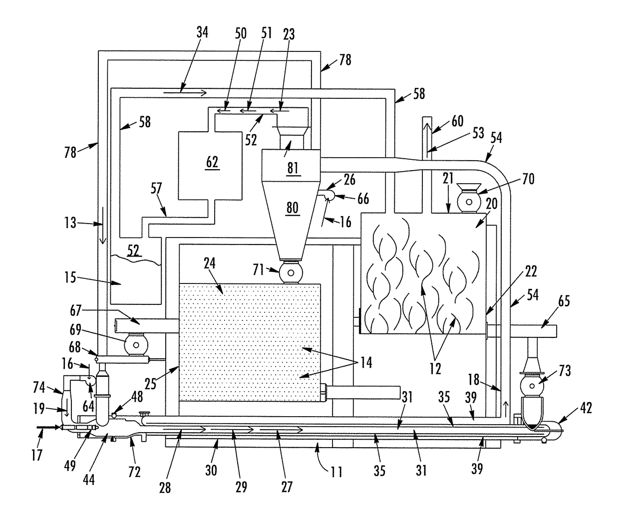
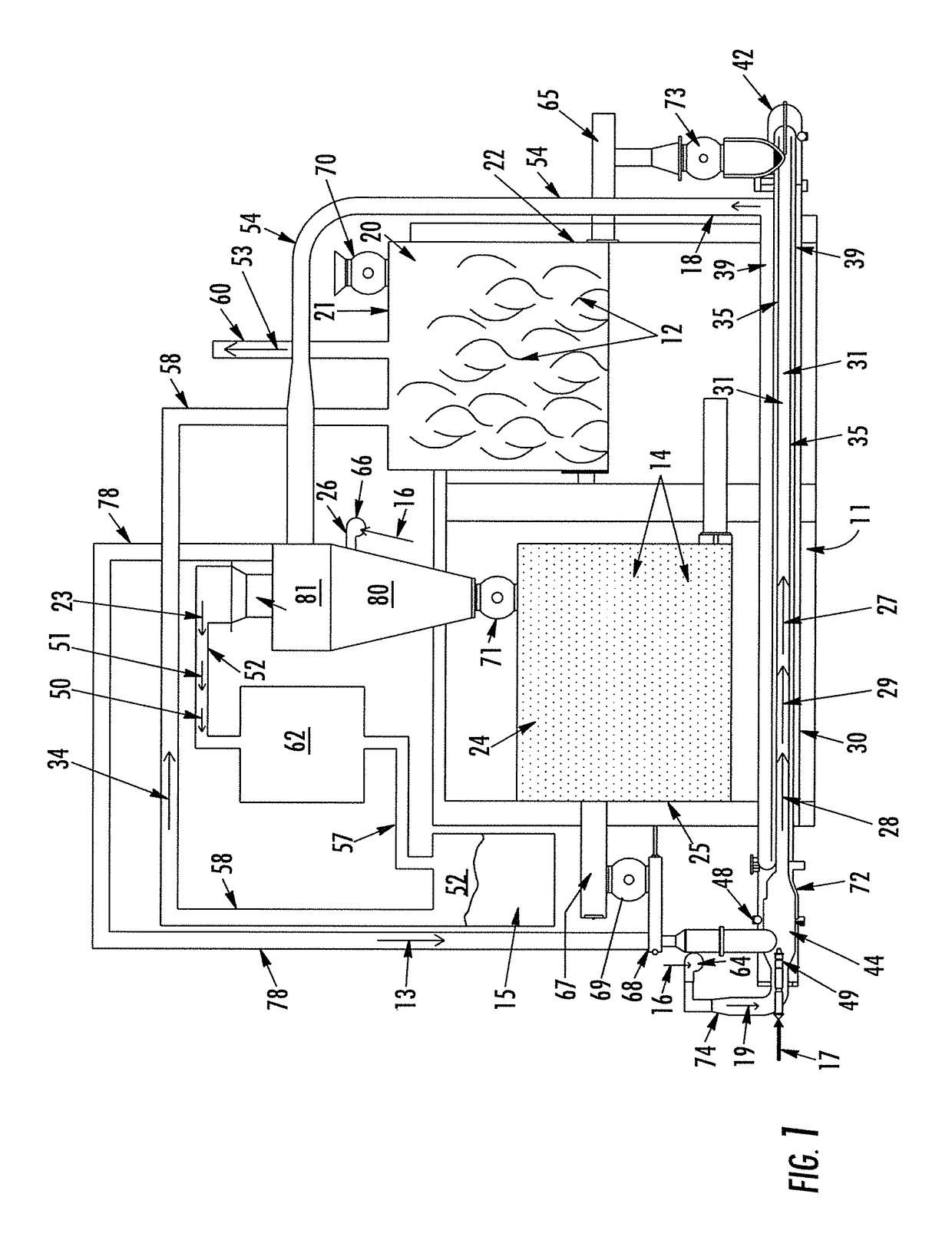
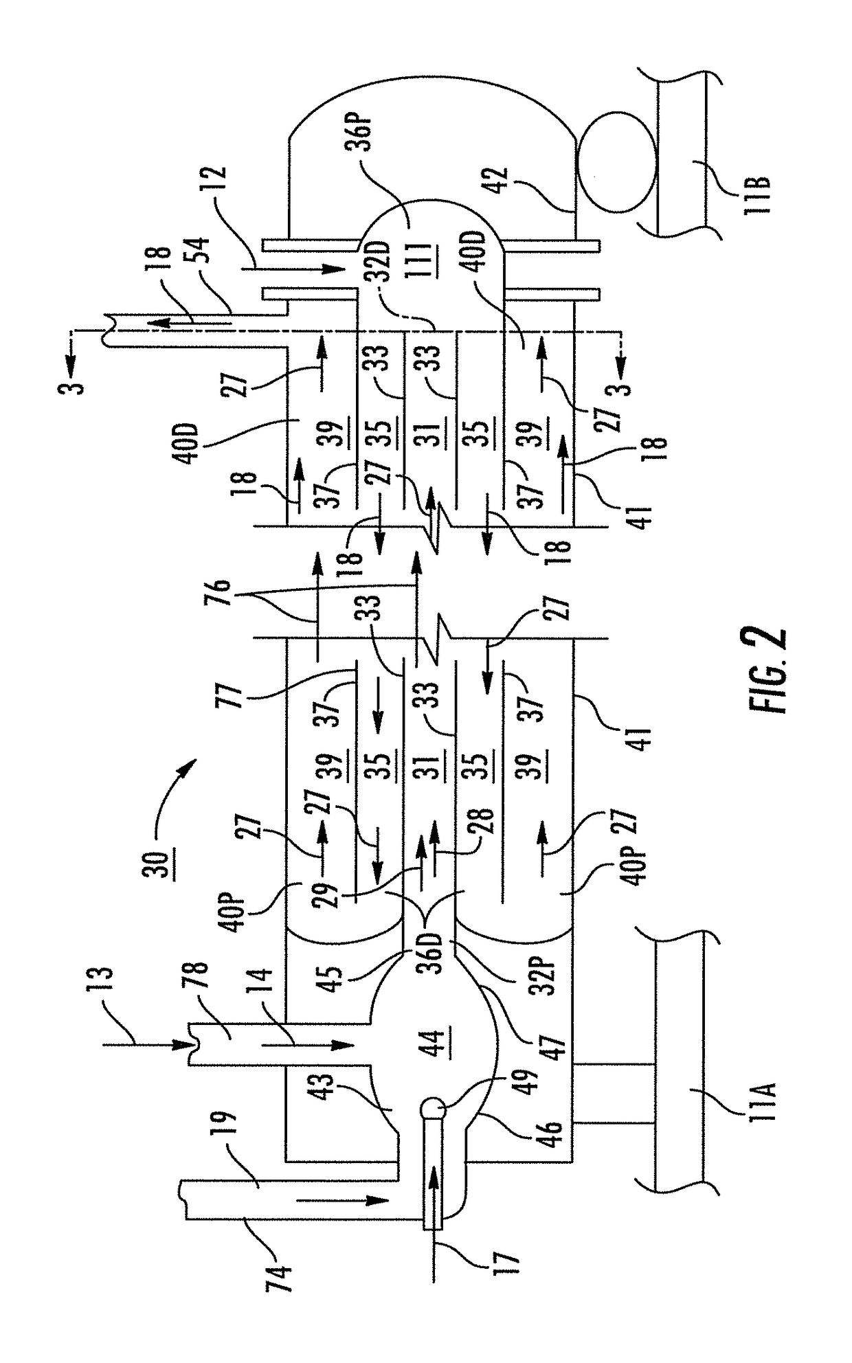
[0052]a fast pyrolysis system in accordance with this invention is depicted in FIGS. 1-4 and designated generally by reference numeral 10.

[0053]Referring now to FIG. 1, the system 10 comprises a biomass feed bin 20 for receiving and delivering biomass 12 into a pyrolysis unit 30, described in detail below. The biomass feed bin 20 is enclosed to provide greater control over the channeling of exhaust 34 (shown as an arrow) from pyrolytic reactions that is fed into the feed bin 20. The biomass 12 is fed through a top 21 of the feed bin 20 using rotary air lock 70. The biomass 12 is delivered into the pyrolysis unit 30 from the feed bin 20 by an auger 65 attached to a lower portion 22 of the biomass feed bin 20. In this way, the biomass feed bin 20 continually feeds new biomass 12 through the system 10 into the unit 30.

[0054]With continued reference to FIG. 1, the biomass feed bin 20 accepts raw biomass 12. The present embodiment envisions receiving this biomass 12 primarily from sawmil...

embodiment 200

[0086]FIGS. 9 and 10 describe a preferred embodiment of the energy-conversion system 200 shown in FIG. 7. Referring first to FIG. 9, raw biomass 204 is ground into cubes at step 220. The ground biomass 204 is then subjected to drying 230. Optimally, the dried biomass 204 has a moisture content of no more than twelve percent. In other embodiments, steam resulting from the drying process 230 is collected for re-use by other parts of the system 200. Hot exhaust gas 320 from the fast pyrolysis system 206 is used in generating electricity 300 which, in turn, is used to aid in the drying process 230. The exhaust gas 320 has a typical temperature of approximately five-hundred degrees Fahrenheit or greater and has a typical oxygen content of approximately fifteen percent. A portion of the exhaust 320 is also used to aid in the rapid pyrolysizing of the biomass 250. Before the exhaust 320 can be used for fast pyrolysis 250, however, it must be deoxygenated. To rid the exhaust 320 of its oxyg...

embodiment 500

[0088]FIGS. 11 and 12 illustrate flow diagrams of another preferred embodiment of an energy-conversion system 500 in accordance with this invention. Referring first to FIG. 11, raw biomass 204 is ground into cubes of between about one-quarter and one-eighth inch. The ground biomass 12 is then subjected to drying 230. Steam from the drying process 230 is collected at step 236 for re-use by other parts of the system or vented to the atmosphere. The biomass 204 is now ground into a powder at step 510, in order to promote a faster reaction time when subjected to fast pyrolysis. In the present embodiment 500, the particle size and shape are optimized for the production of bio-oil plus at step 575. In other embodiments, the process to grind the biomass to a smaller size at 510 will be optimized for the production of bio-oil or other products. The dry powdered biomass 204 is compressed and transported at step 550 to a chamber where it is to be rapidly pyrolysized at step 250. The distance ...


PUM

PropertyMeasurementUnit
temperaturesaaaaaaaaaa
lengthaaaaaaaaaa
lengthaaaaaaaaaa

Abstract

Efficient biomass conversion systems, methods and apparatus utilize a fast pyrolysis unit installed at locations having substantial quantities of biomass, with the biomass fed into the fast pyrolysis unit under pyrolytic reaction conditions, and with exhaust gases containing entrained matter resulting from the pyrolytic reactions being separated into char and bio-fuel constituents.

Description

CROSS-REFERENCE TO RELATED APPLICATIONS[0001]This application is a divisional of U.S. patent application Ser. No. 13 / 740,650 filed Jan. 14, 2013, which is a continuation-in-part of U.S. patent application Ser. No. 13 / 533,258, filed Jun. 26, 2012, (now U.S. Pat. No. 9,217,110), which is a continuation of U.S. patent application Ser. No. 12 / 466,501, filed May 15, 2009, (now U.S. Pat. No. 8,206,471), and a continuation-in-part of application Ser. No. 12 / 361,743 filed Jan. 29, 2009, (now U.S. Pat. No. 8,353,973), which claims priority to provisional application Ser. No. 61 / 053,386, filed May 15, 2008.BACKGROUND OF THE INVENTION[0002]The present invention relates generally to systems, apparatus and methods for the production of energy products from carbonizable material such as biomass, and particularly such systems, apparatus and methods that employ fast pyrolytic reactions.[0003]The United States faces substantial environmental issues from continuing reliance on existing energy sources...

Claims


Application Information

Patent Timeline
Patent Type & Authority Patents(United States)
IPC IPC(8): C10B49/00C10B53/02C10B31/00C10B43/02
CPCC10B49/00C10B31/00C10B43/02C10B53/02C10B49/08C10B49/20C10C5/00Y02P20/145Y02E50/10
Inventor THARPE, JR., JOHNNY M.
Owner AMERICAN BIO ENERGY CONVERTING
Why Eureka
Try Eureka