
Residual map segmentation method for multi-leaf collimator-intensity modulated radiotherapy

a multi-leaf collimator and intensity modulation technology, applied in radiation therapy, diaphragm/collimeter handling, therapy, etc., can solve the problems of substantial deterioration of dose distribution, affecting the actual dosimetric quality of imrt treatment, and affecting the target. not only in the target but also in the nearby critical/normal structur

Inactive Publication Date: 2005-02-08
THE UNIV OF NORTH CAROLINA AT CHAPEL HILL
View PDF32 Cites 45 Cited by
  • Summary
  • Abstract
  • Description
  • Claims
  • Application Information

AI Technical Summary

Benefits of technology

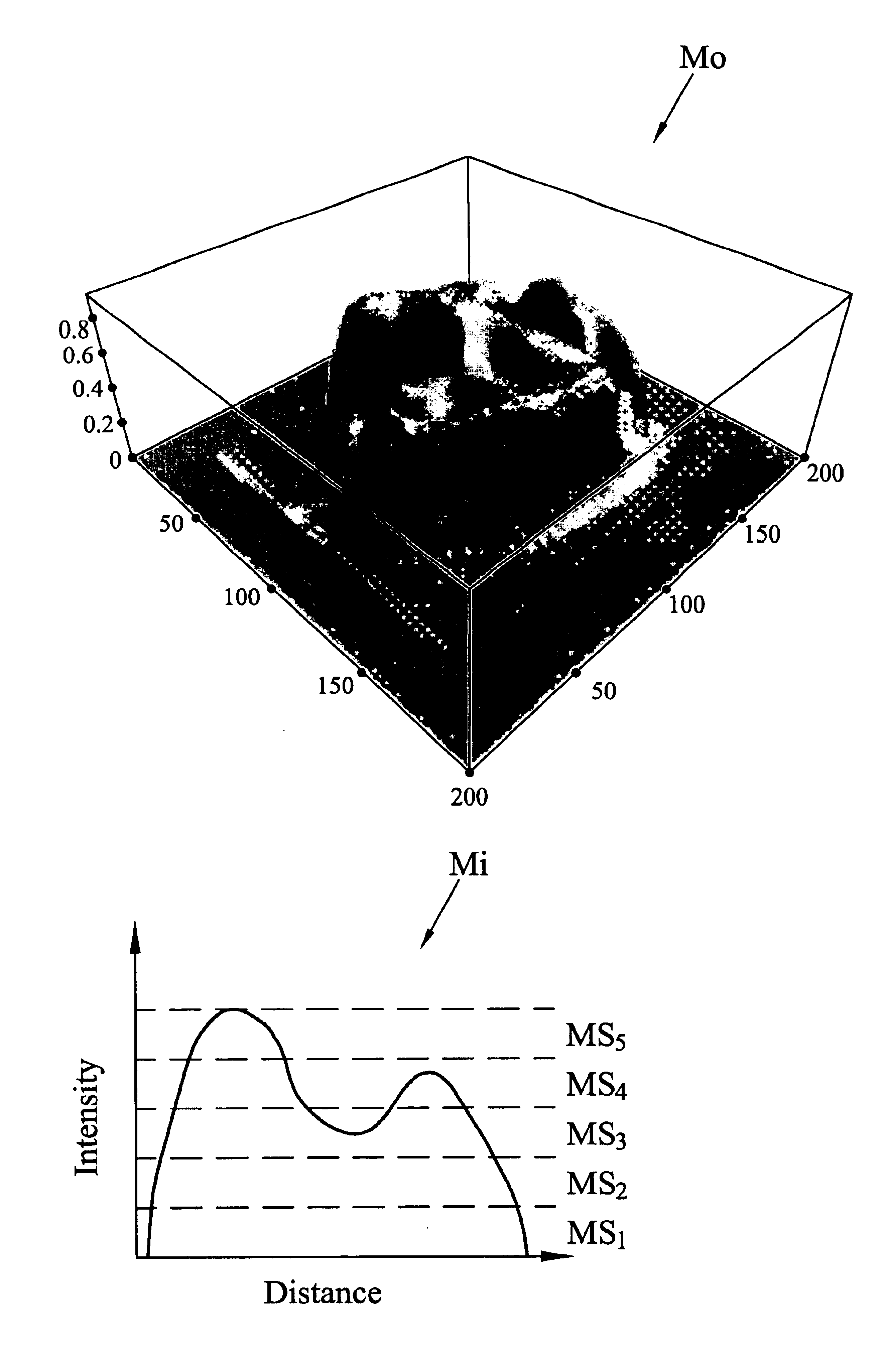
A method is disclosed for generating a sequence of MLC segment-fields for intensity modulated radiotherapy without the use of discrete intensity maps, comprising the following steps. A segment field is generated directly from a continuous intensity map, such as an intensity map derived from a dose optimization. The segment field is generated by determining an optimal collimator configuration that corresponds to a contour of the continuous intensity map

Problems solved by technology

It has been demonstrated that the dosimetric quality of an actual IMRT treatment can be considerably affected by the resolution of the delivery technique compared to the ideal treatment.
The modulation in the MLC-based IMRT techniques, however, varies in both time and space.
This study showed that when the smooth intensity maps originally generated by a dose optimization algorithm are truncated into corresponding discrete maps, a substantial deterioration in dose distributions can result-not only in the target but also in the nearby critical / normal structures.
The treatment quality sometimes can be improved by increasing the intensity level resolution of the intensity map, but at the cost of increasing the number of segments required and thus reducing the efficiency of the treatment.
However, this hardware solution has the drawback of increasing the mechanical complexity and thus the cost of the device.
Unfortunately, the discreteness used in existing MLC-based IMRT dose optimization and segmentation algorithms is considerably stricter than the intrinsic limitations of the existing MLC delivery hardware.
The segmental MLC technique also suffers from longer treatment irradiation time.

Method used


Image

  • Residual map segmentation method for multi-leaf collimator-intensity modulated radiotherapy
  • Residual map segmentation method for multi-leaf collimator-intensity modulated radiotherapy
  • Residual map segmentation method for multi-leaf collimator-intensity modulated radiotherapy

Examples


Embodiment Construction

The segmentation method disclosed herein is designed to fully utilize the functionalities of existing MLC hardware, and to minimize the effects of the intrinsic discreteness of the MLC-based delivery technique in intensity modulation generation. It is hypothesized herein that not every part of the intensity map has the same influence to the treatment dosimetry, or the closeness of the treatment dosimetry to the optimization objective. It is further hypothesized that intensity map regions exhibiting high gradients (i.e., the intensity changes drastically in space) have stronger influences on the closeness of the treatment result to the optimization objective than the regions of low gradients. It has been found that the high gradient regions of the intensity map often divide the planned treatment volume (PTV) and the nearby organ at risk (OAR). Hence, preserving this region of the map is crucial for the intended tumor coverage and OAR sparing. Therefore, when attempting to deliver int...


PUM


Abstract

In a method for sequentially generating segment fields for use in delivering intensity modulated radiotherapy an input continuous intensity map is generated. A segment field is generated directly from the input intensity map. A residual continuous intensity map is generated that is based on the respective photon fluence contributions from the input intensity map and a fractionally intensity map corresponding to the segment field. These steps are repeated for a number of iterations to generate a like number of additional segment fields and residual maps derived therefrom. In each iteration, the residual map generated in the previous iteration is used as the input intensity map.

Description

TECHNICAL FIELDThe present invention generally relates to intensity-modulated radiotherapy (IMRT). More particularly, the invention relates to the optimized configuration of multi-leaf collimator leaves for delivery of IMRT.BACKGROUND ARTFor any given radiation treatment procedure, a common goal is to deliver an adequate, therapeutically effective dosage of radiation to the tumor while minimizing potentially damaging dosage exposure to nearby critical organs and other tissues (termed organs at risk or OAR). Intensity-modulated radiotherapy (IMRT) is a popular new technology to customize radiation treatment in accordance with this goal for each patient. The most widely available apparatus for delivering IMRT procedures for cancer patients is a medical linear accelerator (LINAC). LINAC-based IMRT treatment apparatuses are described in, for example, U.S. Pat. Nos. 5,663,999; 6,134,296; 6,240,161; 6,240,162; 6,330,300; 6,335,961; 6,349,129; 6,353,655; 6,449,335; 6,473,490; and 6,477,229...

Claims


Application Information

Patent Timeline
IPC IPC(8): A61N5/10G21K1/04G21K1/02
CPCG21K1/046G21K1/04A61N5/1042A61N5/1036
Inventor CHANG, SHA
Owner THE UNIV OF NORTH CAROLINA AT CHAPEL HILL
Learn More