Another aspect of the present invention is an identity verification system, the verification system comprising: (a) a plurality of referenced data input devices wherein each referenced data input device is associated with a data identification code; (b) a plurality of entry means for recording biometric data, wherein each entry means is associated with a biometric identification code; (c) a plurality of display means for displaying information to a system operator; (d) a communication control device remote from the entry means, the data input devices and the display means, said communication control device having (i) receiving means for receiving a set of biometric data from the entry means linked to the biometric identification code and a set of input data from the data input device linked to the data identification code, (ii) a first conversion means for selectably capturing a portion of the set of biometric data received from the entry means and converting said portion of captured biometric data into a compressed digital file of the captured biometric data linked to the biometric identification code, (iii) a second conversion means for formatting the set of input data into a network protocol standard linked to the data identification code, (iv) transmitting means for transmitting data from the communication control device to the display means, and (v) connecting means for connecting the first conversion means to the entry means, the second conversion means to the data input device, the transmitting means to the display means, and the communication control device to a computer network; and (e) at least one system central processing unit remote from the communication control device and in direct communication with the communication control device having (i) an installed biometric recognition system, (ii) a first processor means for generating a biometric template from the captured biometric data using the installed biometric recognition system, (iii) storage means for storing a set of biometric templates generated by the biometric recognition system in a biometric database, (iv) searching means for searching the biometric database for a stored biometric template linked with an identifying parameter, (v) a second processor means for comparing and scoring the correspondence of two biometric templates using the installed biometric recognition system; and (vi) communication means for bi-directional communication with the communication control device.
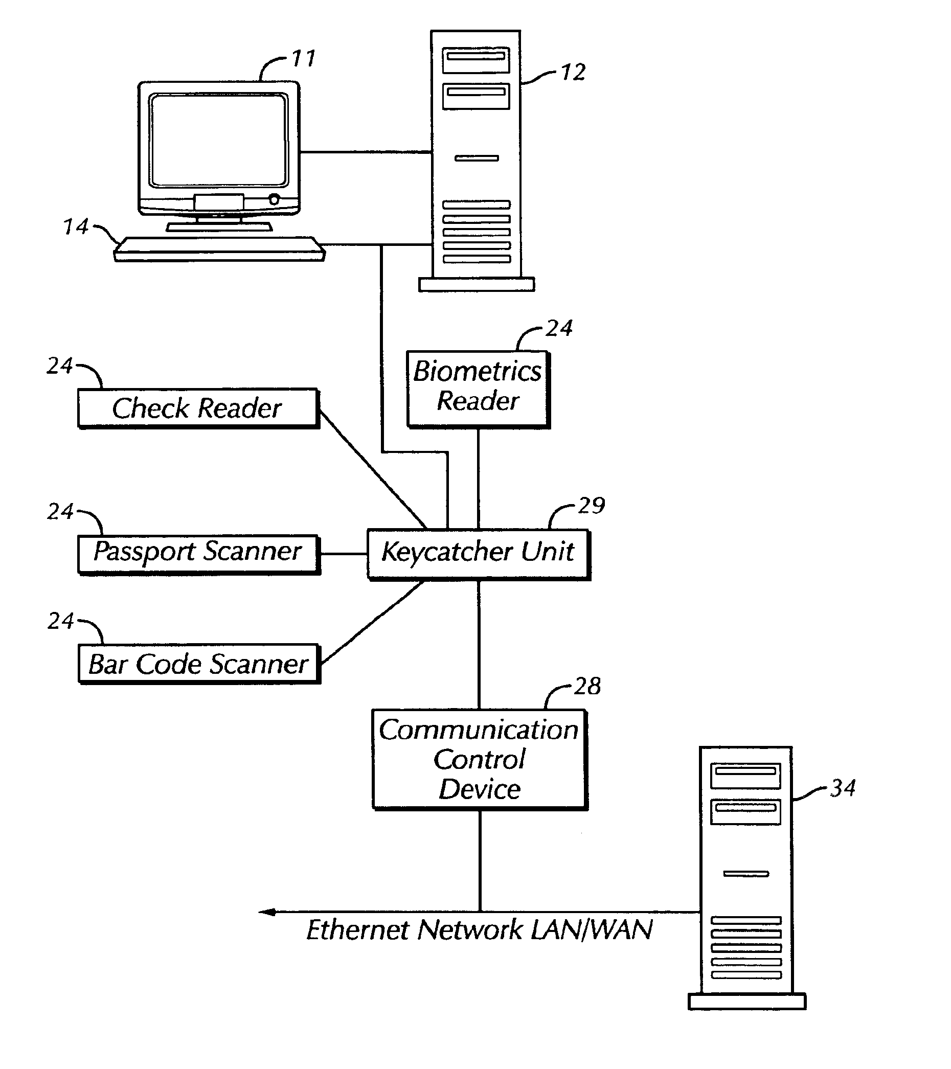
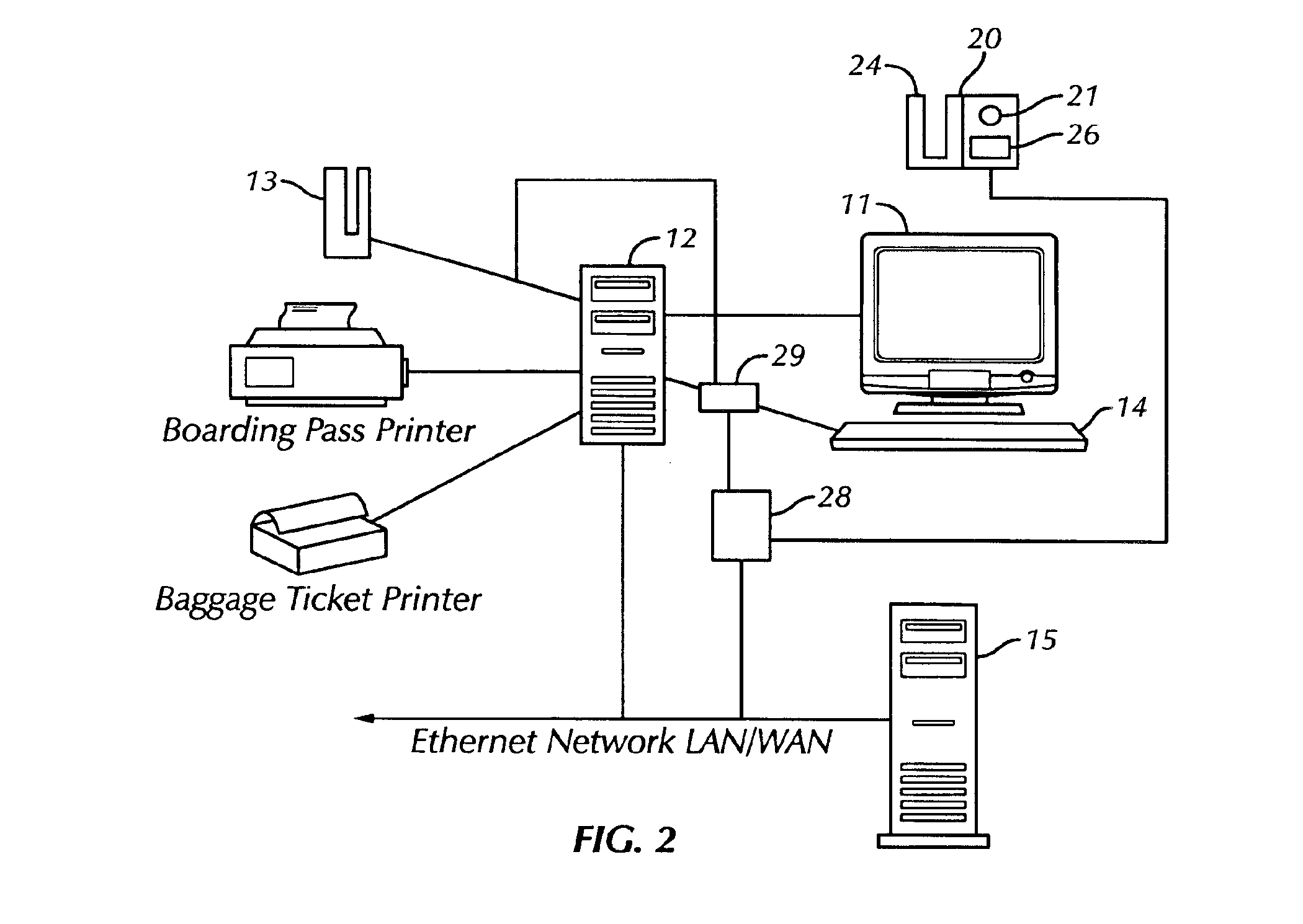
Yet another aspect of the present invention is an identity verification system, the verification system comprising: (a) a plurality of data input stations, each data input station comprising (i) a referenced data input device associated with a data identification code, (ii) at least one entry means for recording a set of biometric data, wherein each entry means is associated with a biometric identification code, and (iii) a display means associated with the data input device and the entry means; (b) a communication control device remote from said data input stations, said communication control device having (i) receiving means for receiving the set of biometric data linked with the biometric identification code and a set of input data from the data input device linked with the data identification code, (ii) a first conversion means for selectably capturing a portion of the set of biometric data received from the entry means and converting said portion of captured biometric data into a compressed digital file of the captured biometric data linked to the biometric identification code, (iii) a second conversion means for formatting the set of input data into a network protocol standard linked to the data identification code, and (iv) transmitting means for transmitting data from the communication control device to the display means; (c) a plurality of keycatcher units; (d) a plurality of interactive local communication stations, each communication station comprising (i) a local central processing unit, (ii) a keyboard, (iii) a monitor, and (iv) a data input apparatus; and (e) a system central processing unit remote from the communication control device and in direct communication with the communication control device having (i) an installed biometric recognition system, (ii) a first processor means for generating a biometric template from the captured biometric data using the installed biometric recognition system, (iii) a second processor means for comparing and scoring the correspondence of two biometric templates using the installed biometric recognition system; (iv) storage means for storing a set of biometric templates generated by the biometric recognition system in a biometric database, (iv) searching means for searching the biometric database for a stored biometric template linked with an identifying parameter, and (v) communication means for bi-directional communication with the communication control device.
Still yet another aspect of the present invention is an identity verification system, the verification system comprising: (a) a plurality of referenced data input devices wherein each referenced data input device is associated with a data identification code; (b) a plurality of cameras for recording photographic images, wherein each camera is associated with a camera identification code; (c) a display means for displaying information to a system operator; (d) a communication control device remote from the data input devices, the cameras and the display means, said communication control device including (i) a camera server having a video engine in communication with at least one camera, wherein the video engine selectably captures a set of photographic images taken with the camera and co

