

Air flow sensing and control for animal confinement system
a technology which is applied in the field of air flow sensing and control of air flow in animal confinement systems, can solve the problems of not having the capability to monitor and maintain the desired air flow within the cage and rack or otherwise monitor and control the environment in the cage and rack, and the current rack and cage ventilation system cannot provide rack and/or cage-level control of the environment in the rack and/or cage. the effect of accurate measurement of the flow rate and minimizing the energy loss of the flow
- Summary
- Abstract
- Description
- Claims
- Application Information
AI Technical Summary
Benefits of technology
Problems solved by technology
Method used
Image

Examples
Embodiment Construction
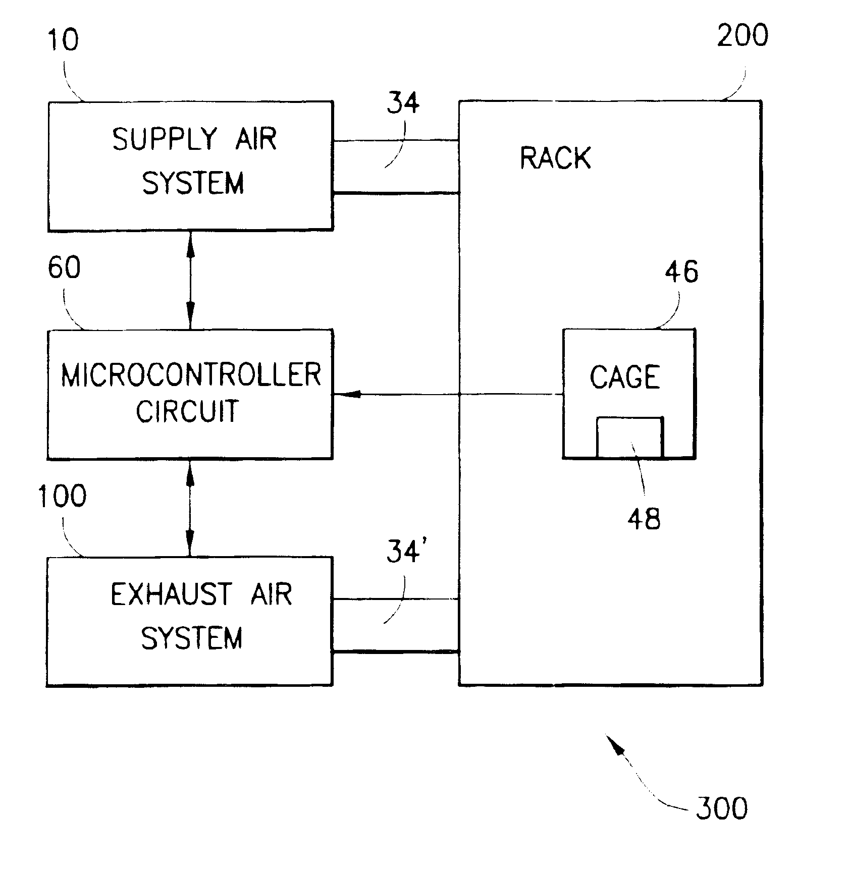
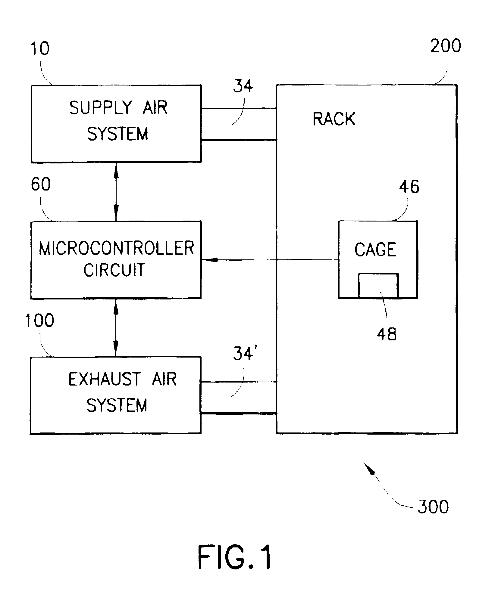
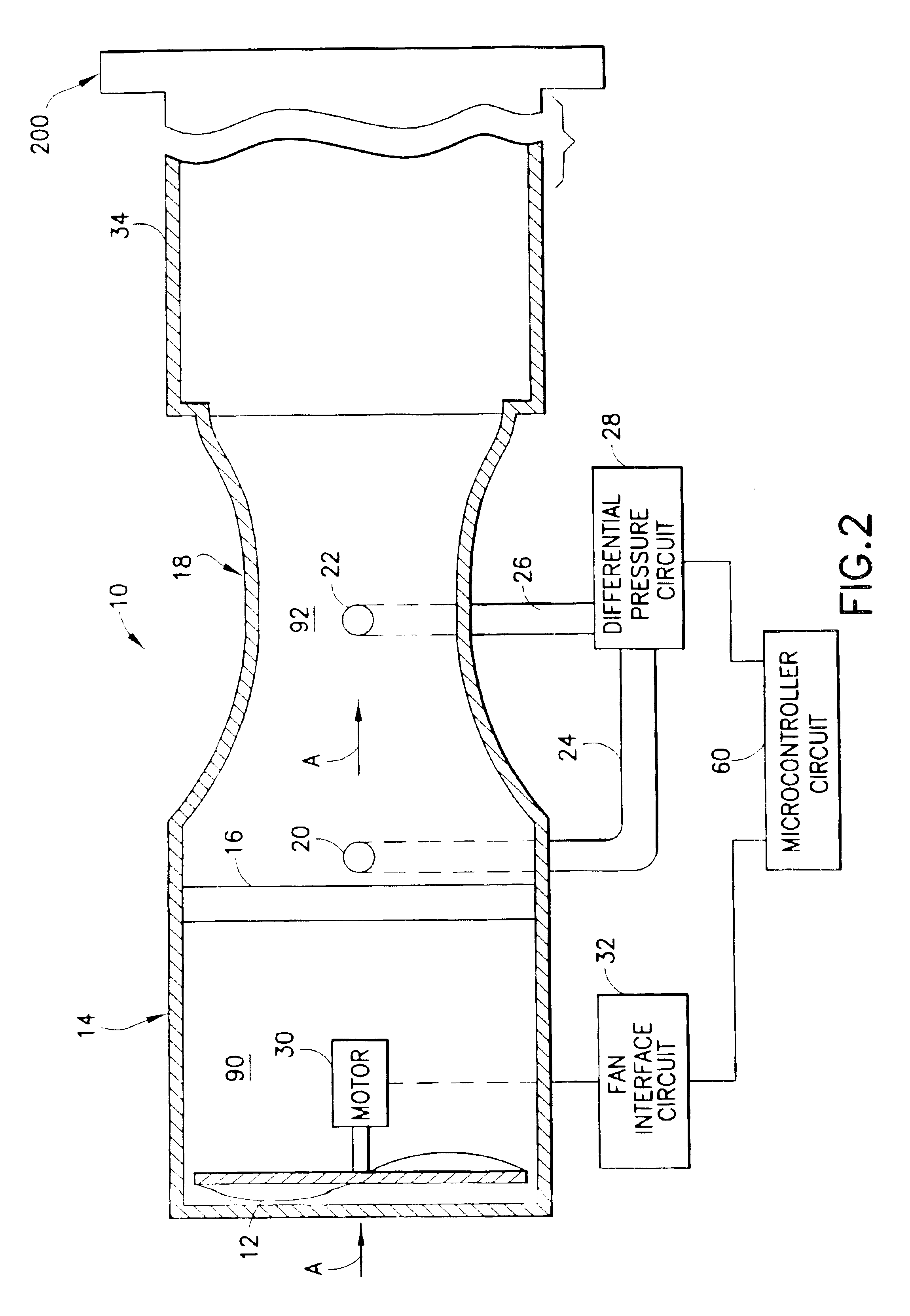
The present invention is directed to an environmental monitoring and controlling system for a ventilated cage and rack system. The present invention monitors and measures air flow in the rack at either the rack or cage level. At the rack level, pressure in a supply air system is measured at two pressure points to accurately monitor the air flow rate into the rack. In addition, pressure may be measured at two pressure points in an exhaust air system to accurately monitor the air flow rate out of the rack. At the cage level, a cage may be equipped with a highly accurate flow sensor, consisting of a Venturi tube and thermistor, to monitor the air flow rate in a cage located at any cage position in the rack. For example, the cage may be located in a position known to experience the lowest air change per hour rate. Control of the supply air system may thus be effected by the cage and determined by the air flow rate (i.e., air change per hour rate) detected at the cage level. Control of a...
PUM
 Abstract
Description
Claims
Application Information