Structural walls

a structure wall and wall plate technology, applied in the direction of girders, building repairs, rod connections, etc., can solve the problems of high manufacturing cost, weakened upper frame members by the way they are constructed, and still require a cost, so as to achieve the effect of being cheap to manufactur

Inactive Publication Date: 2005-02-15
STEELER
View PDF19 Cites 115 Cited by
  • Summary
  • Abstract
  • Description
  • Claims
  • Application Information

AI Technical Summary

Benefits of technology

An object of the present invention is to provide a simplified framing system in which the studs and the upper and lower channel members are all relatively inexpensive to manufacture, and the screw fasteners u

Problems solved by technology

A problem with most of the systems disclosed by Smolik U.S. Pat. No. 4,805,364; Paquette U.S. Pat. No. 5,127,203; Brady U.S. Pat. No. 5,127,760 and DeFramesco et al.
U.S. Pat. No. 5,313,752 is that the components of the systems are expensive to manufacture.
Another problem of the systems disclosed by Paquette U.S. Pat. No. 5,127,203 and Brady U.S. Pat. No. 5,127,760 is that the upper frame members are weakened by the way they are constructed.
Although they are unused, they stil

Method used


Image

  • Structural walls
  • Structural walls
  • Structural walls

Examples


Embodiment Construction

Referring to the drawing, the structure shown by FIGS. 1-13 is essentially the same structure that is disclosed by FIGS. 20-22 of my prior application Ser. No. 09 / 293,074, filed Apr. 16, 1999 (now U.S. Pat. No. 6,374,558 B1, granted Apr. 23, 2002), and also disclosed by FIGS. 1-6 of my copending application Ser. No. 10 / 035,488, filed Oct. 19, 2001, as a continuation-in-part of the prior application Ser. No. 09 / 293,074.

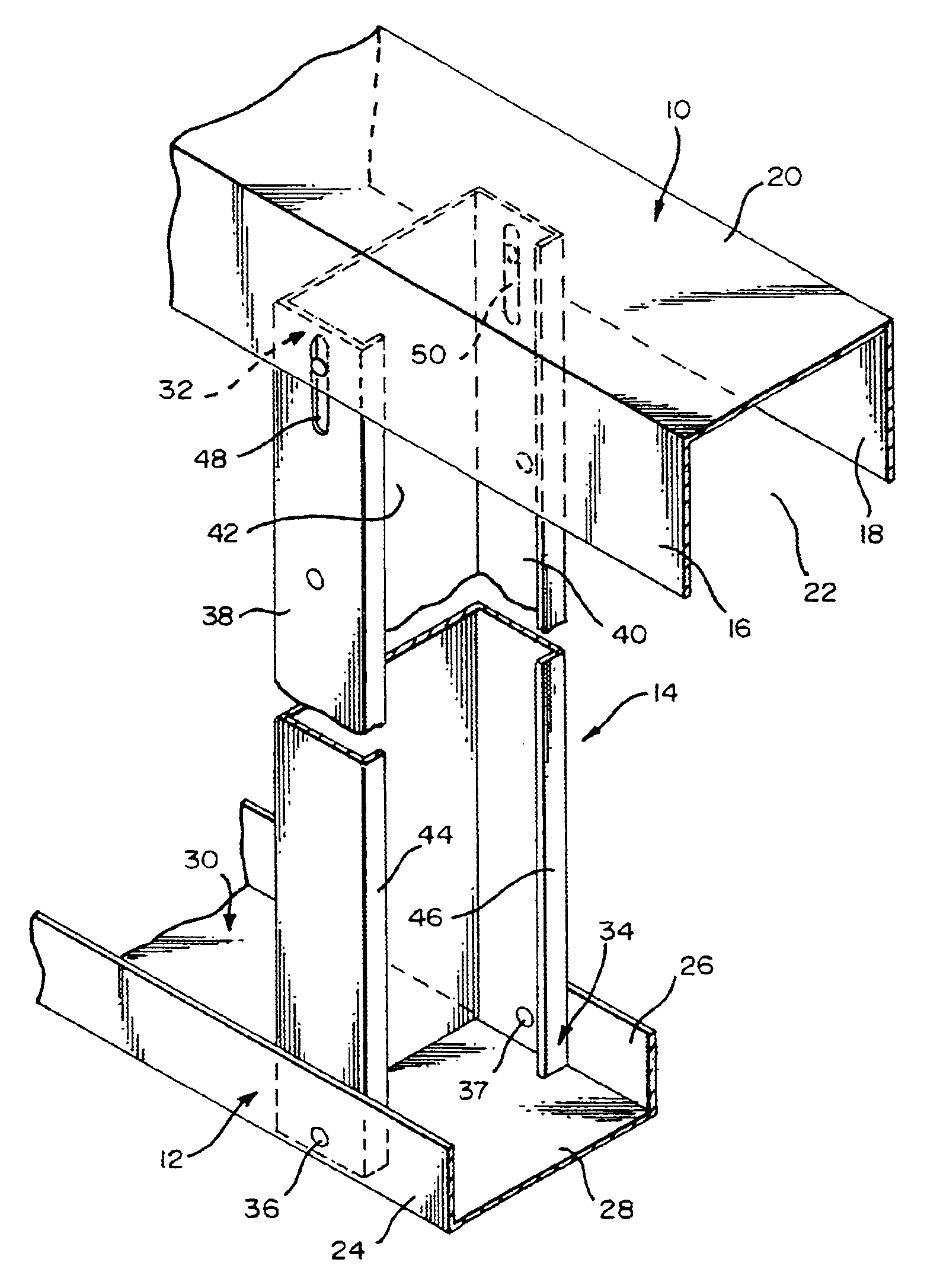
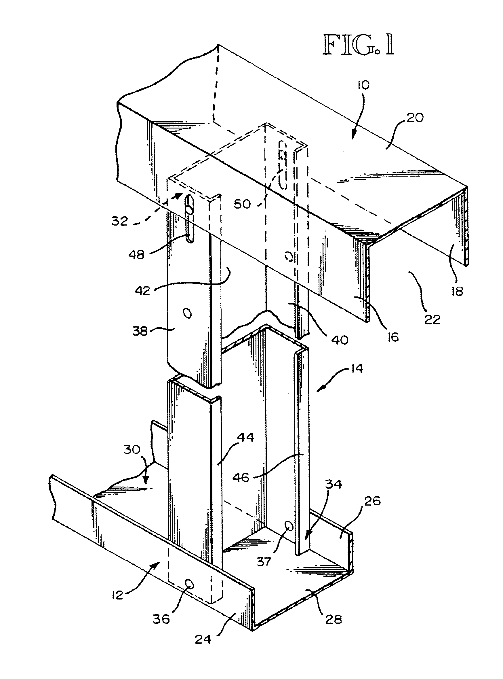
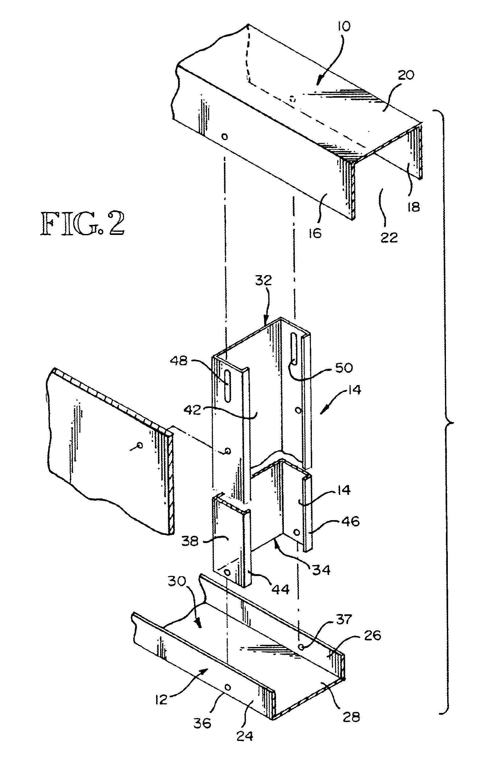
Referring specifically to FIGS. 1 and 2 of the drawing, the framing structure that is illustrated comprises an upper channel member 10, a lower channel member 12 and a stud 14. All three of these members 10, 12, 14 are constructed from sheet-metal. The upper channel member 10 is connected to a suitable overhead support, and the lower channel member 12 is connected to a suitable lower support. Channel member 10 includes opposite sidewalls 16, 18 interconnected at their upper edges by a web 20. The sidewalls 16, 18 depend from the web 20 and the three members 16, 18, 20 ...


PUM


Abstract

A plurality of studs (14) are spaced apart relative to each other. Upper end portions (32) of the studs fit into an upper channel space (22) and lower end portions (34) fit into a lower channel space (30). The lower channel space (30) is defined in part by a pair of spaced apart sidewalls (24, 26). Screw fasteners (52) extend through the sidewalls (24, 26) and connect them to the lower end portion (34) of the stud (14). The studs (14) have upper ends that are spaced from a web (20) forming the upper boundary of the upper channel space (22). Vertical elongated slots (48, 50) are provided in the sidewalls (38, 40) of the studs (14). Screw fasteners extend through the sidewalls (16, 18) of the upper channel member (10) and then extend into and through the slots (48, 50). The heads of the screw fasteners (52) bear against the sidewalls (16, 18) when the screw fasteners (52) are tightened. This firmly connects the screw fasteners (52) to the sidewalls (16, 18), but there is no connection of the screw fasteners (52) to the upper end portions of the studs (14). When the screw fasteners (52) are tightened, there is no clamping action between the heads (54) of the screw fasteners (52) and the upper end portions (32) of the studs (14). As a result, the studs (14) are completely free to move up and down relative to the upper channel member (10), within limits established by the lengths of the slots (48, 50).

Description

TECHNICAL FIELDThe present invention relates to wall structures composed of sheet-metal frame members and to a method of constructing wall structures from such sheet-metal frame members. More particularly, the invention provides a wall structure in which a horizontal frame member at the top of the wall structure, and an overhead structure to which it is connected, are able to move vertically relative to the remainder of the wall structure, such as during an earthquake or as settlement occurs.BACKGROUND OF THE INVENTIONMy aforementioned U.S. Pat. No. 6,374,558 includes a comprehensive Background of the Invention. Additional background information is set forth by U.S. Pat. No. 4,805,364, granted Feb. 21, 1989 to Robert A. Smolik; buy U.S. Pat. No. 5,127,203, granted Jul. 7, 1992 to Robert F. Paquette; by U.S. Pat. No. 5,127,760, granted Jul. 7, 1992, to Todd A. Brady; by U.S. Pat. No. 5,685,121, granted Nov. 11, 1997 Frank De Framcesco and Joseph D. Alumbo; and by U.S. Pat. No. 5,313,...

Claims


Application Information

Patent Timeline
IPC IPC(8): E04B2/74E04B2/82E04C3/07E04C3/04
CPCE04B2/7457E04B2/825E04C3/07E04B2/7411Y10T403/4691E04C2003/0434E04C2003/0473Y10T403/46E04C2003/0421F16B2200/403
Inventor SUROWIECKI, MATT F.
Owner STEELER
Why Eureka
Try Eureka