Windrow forming system for a crop harvesting header

a technology of windrow forming and crop harvesting, which is applied in the direction of crop conditioners, mowers, agriculture tools and machines, etc., can solve the problems of increasing drying time and forming concentrated crop streams, and achieve the effect of providing the adjustment more quickly

Inactive Publication Date: 2005-02-15
MACDON INDS
View PDF11 Cites 49 Cited by
  • Summary
  • Abstract
  • Description
  • Claims
  • Application Information

AI Technical Summary

Benefits of technology

The adjustment can be carried out simply by unbolting and sliding the sheets each relative to the next. However a more user-friendly system can use a crank and slide guide system which provides the adjustment more quickly and without the necessity for the user accessing the area underneath the header.

Problems solved by technology

A common problem therefore, is that of controlling and guiding the web of crop material issuing from the conditioner and controlling this to reduce in width to form the narrower the windrow which is required.
In many cases, conventional designs have the disadvantage of the formation of concentrated crop streams as the edges of the flow are deflected inward to form a windrow narrower than the conditioner.
Such concentrated crop streams interfere with the requirement for uniformity or constant density and thus will increase drying time.

Method used


Image

  • Windrow forming system for a crop harvesting header
  • Windrow forming system for a crop harvesting header
  • Windrow forming system for a crop harvesting header

Examples


Embodiment Construction

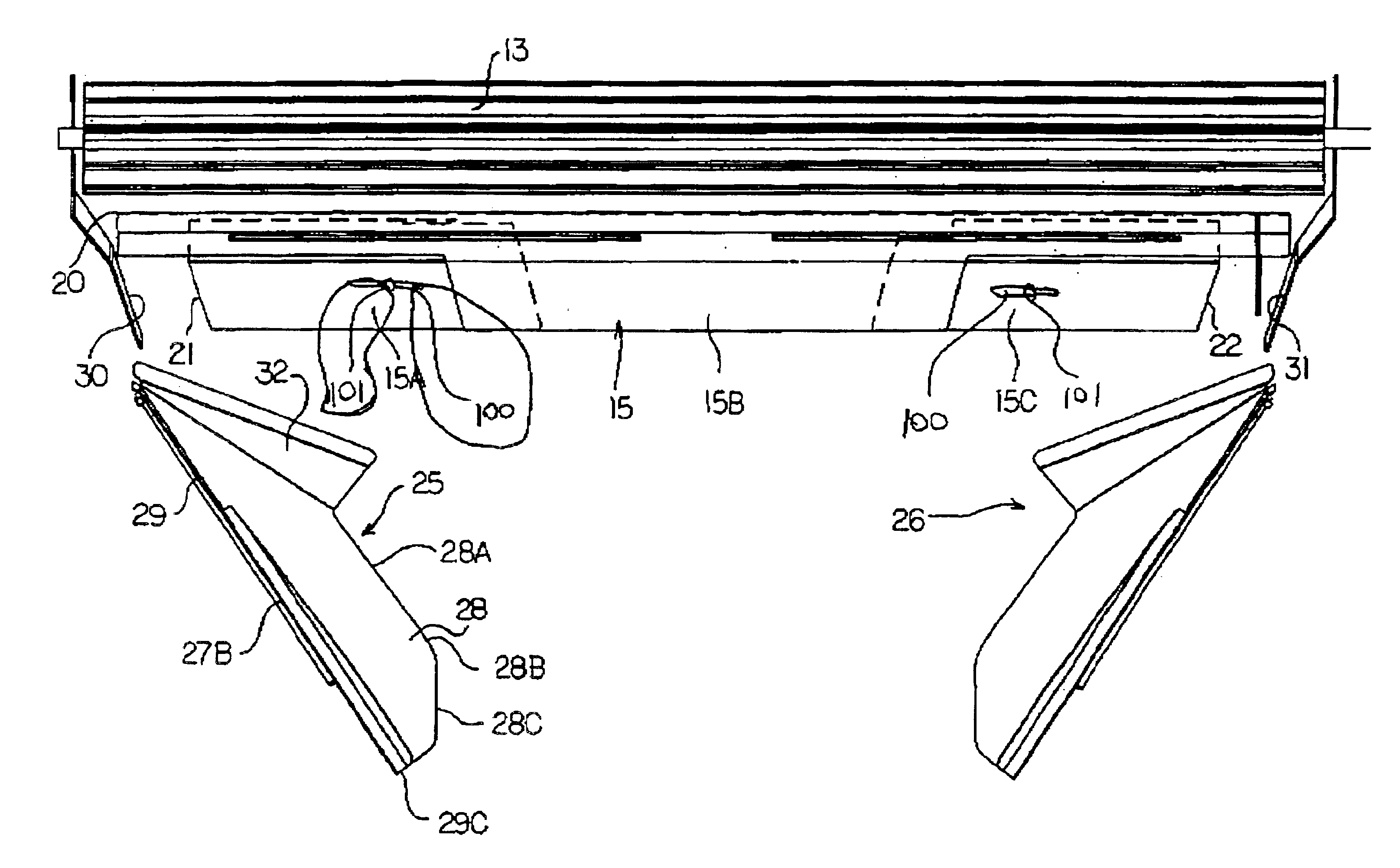
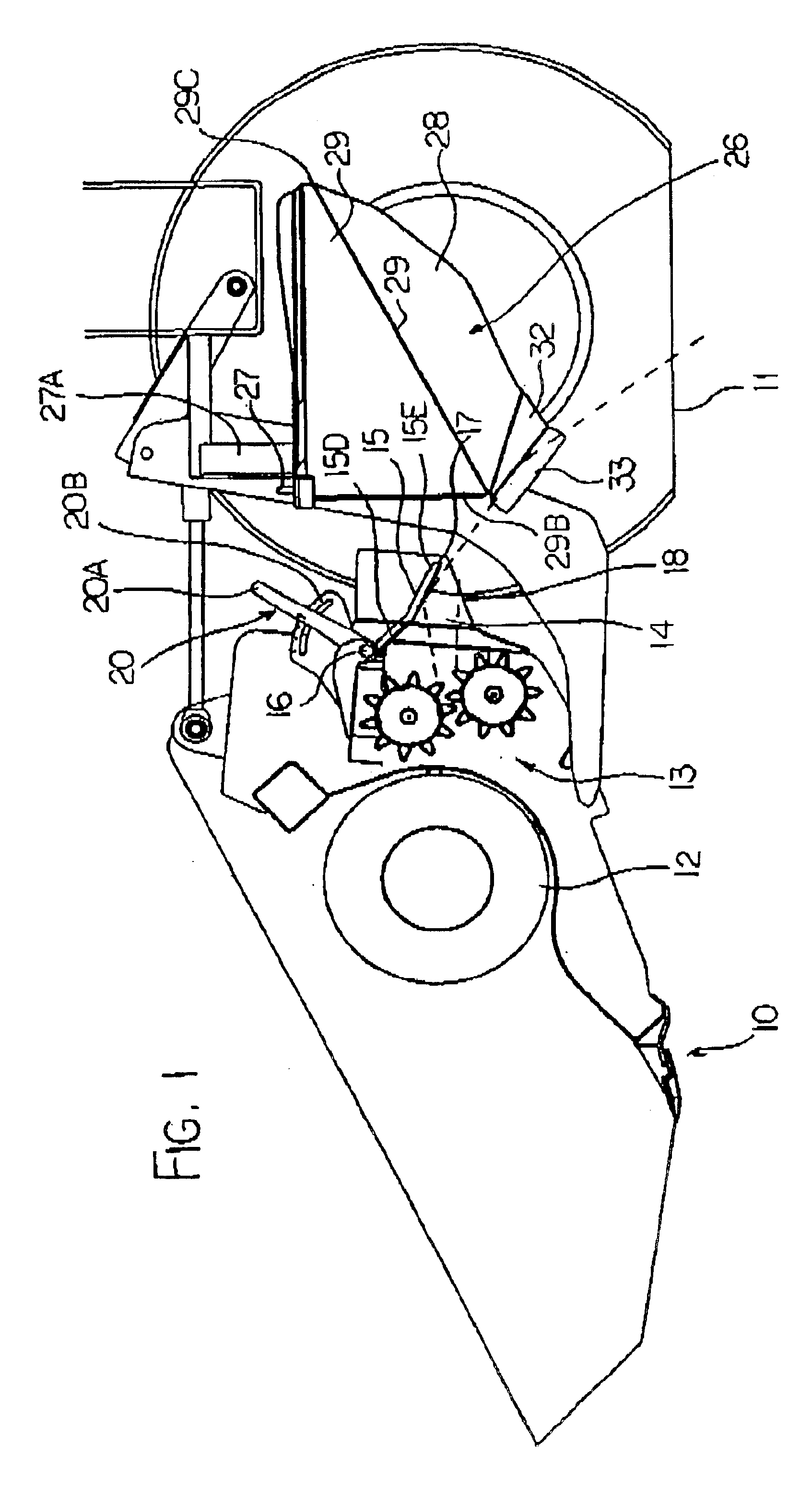
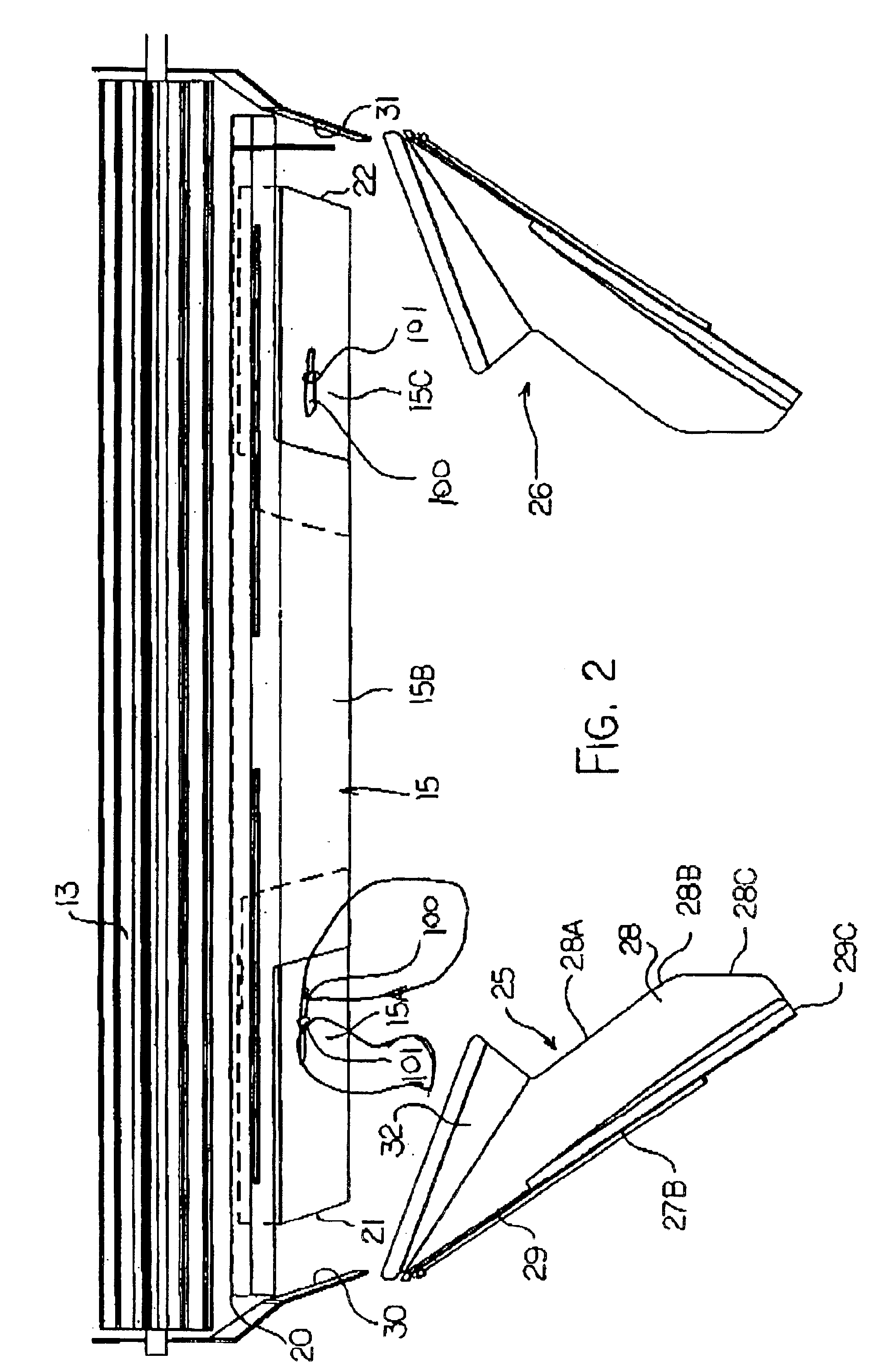
A header shown schematically in FIG. 1 includes a cutter bar 10 of a conventional construction which cuts crop from ground 11 in advance of the cutter bar and discharges that crop onto a crop convergence or conveying system generally indicated at 12 which feeds the crop to a conditioning assembly generally indicated at 13.

The cutter bar can be of many different types including sickle knives, rotary cutters and others depending upon crop requirements, as well known to one skilled in the art. The convergence system 12 can be also be of various different types including drapers, augers, guide surfaces and the like which simply act to converge the crop or carry the crop to the conditioner assembly 13.

The conditioner assembly 13 can also be of various different types including fluted rollers, pressure rollers, flail rollers and others, again depending upon crop type and condition.

In the conditioner assembly, the crop is generally compressed to form a web which emerges from the conditione...


PUM


Abstract

A windrow is formed by discharging the crop rearwardly from a crop conditioner, engaging a center part of the web with a center deflector panel which is adjustable in width so as to direct that portion of the web, selected to match the intended width of the windrow, in contact with the center deflector panel downwardly toward the ground leaving two side portions which are not deflected and thus move to a height above the center portion, and engaging each of the side portions with a side deflector panel so that the side portion is redirected from a position at one side of the center portion and above the center portion to a position on top of the center portion.

Description

This invention relates to a windrow forming system for crop emerging from the conditioner of a crop harvesting header.BACKGROUND OF THE INVENTIONThe term “header” as used commonly and as used in this specification is intended to include both headers carried on self propelled machines, which may therefore not include wheels mounted on the header itself, and headers which are towed behind a tractor and thus may include wheels attached to the header frame or to a component supporting the header.Forage harvesting machines that condition forage and then deposit the forage into a windrow for drydown and subsequent harvesting are commonly used. Various types of forming baffles, fins, and shields are used to process the forage as it is ejected from the conditioner so that the windrow width, shape, uniformity and density are controlled.A variety of preferences on width and height are common are used depending on operator preferences. These depend on climate factors such as wind, sun, precipi...

Claims


Application Information

Patent Timeline
Patent Type & Authority Patents(United States)
IPC IPC(8): A01D57/00A01D82/00A01D57/26
CPCA01D82/00A01D57/26
Inventor SNIDER, GEOFFREY U.
Owner MACDON INDS
Why Eureka
Try Eureka