Structure of pile head joint portion and pile head fitting tubular body

a technology of tubular body and pile head joint, which is applied in the direction of bulkhead/pile, protective foundation, construction, etc., can solve the problems of difficult to secure a quality of the pile head joint portion, difficult to greatly shorten the process required for all the construction of the pole and the bottom board, and achieve the effect of stable quality and shortening the process

Inactive Publication Date: 2005-02-15
SPLICE SLEEVE JAPAN +1
View PDF5 Cites 6 Cited by
  • Summary
  • Abstract
  • Description
  • Claims
  • Application Information

AI Technical Summary

Benefits of technology

[0012]Further, another object of the present invention is to provide a structure of a pile head joint portion and a pile head fitting tubular body which can secure a stable quality.
[0013]Further, the other object of the present invention is to provide a structure of a pile head joint portion which can greatly shorten the process required for constructing a pile body in a pile base structure, and a board joined with the pile body and supporting an upper structure.

Problems solved by technology

(a) The reinforcing bar in the board supporting the upper structure, the reinforcing bar protruding from the pile head portion and the reinforcing bar reinforcing the same are complicated, or the bearing plate provided in the pile head portion is in the way, whereby it is hard to securely charge the concrete to the pile head joint portion, so that it is hard to secure a quality of the pile head joint portion.
(b) After constructing the pile body, since the upper structure is constructed by the cast-in-place concrete after processing the pile head portion, it is hard to shorten the process.
Further, in the case of constructing the pile body in accordance with the micro pile construction method, the process required for constructing the pile body is shorter than the general pile body construction, however, since the bottom board is constructed by the cast-in-place concrete, it is hard to greatly shorten the process required for all of the construction of the pole and the bottom board.

Method used


Image

  • Structure of pile head joint portion and pile head fitting tubular body
  • Structure of pile head joint portion and pile head fitting tubular body
  • Structure of pile head joint portion and pile head fitting tubular body

Examples


example

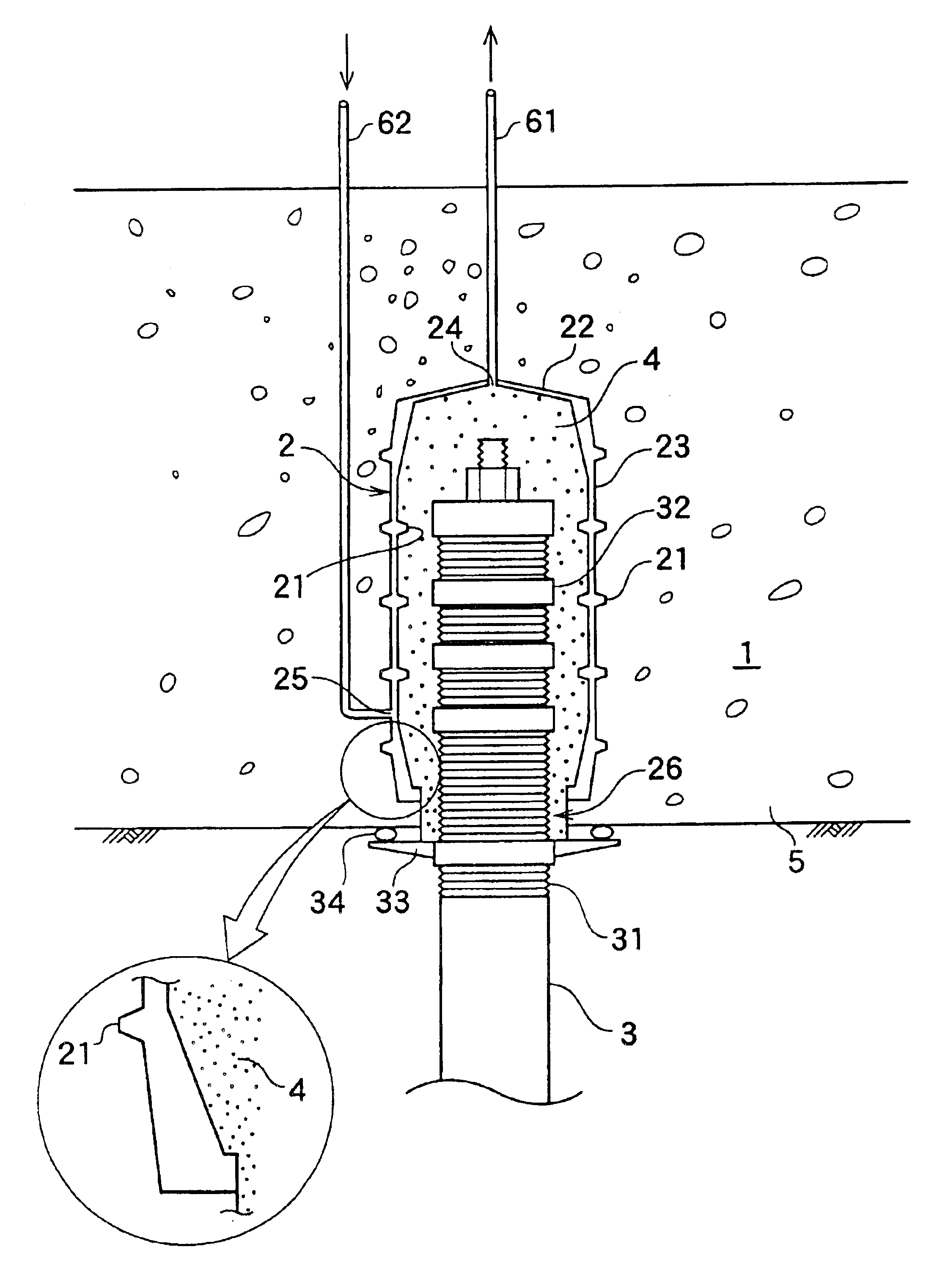
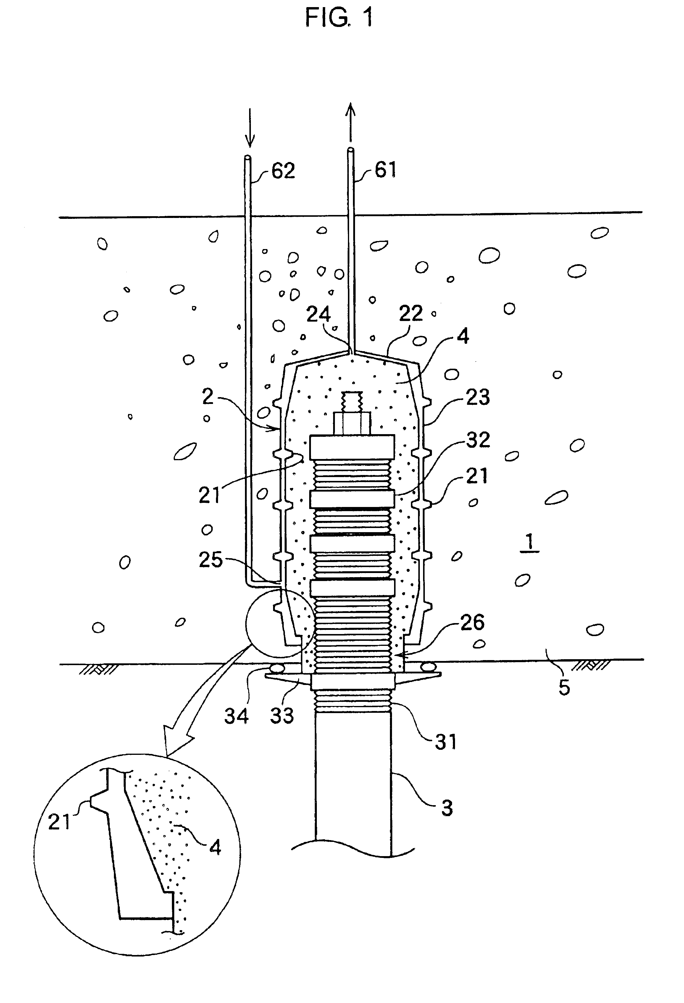
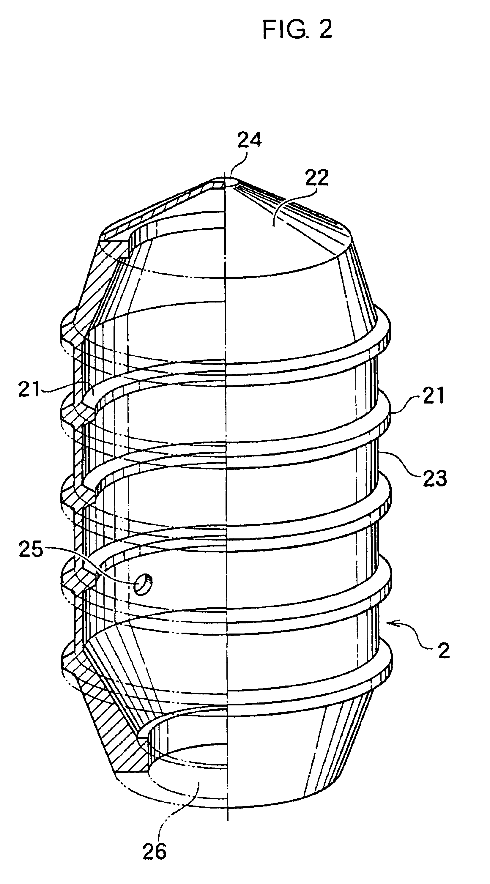
[0064]The pile head fitting tubular body 2 can be manufactured such that an inner diameter of the opening portion 26 is about 300 mm, and a length of the side plate 23 in an axial direction of the tube body is about 650 mm.

[0065]Further, the pile body 3 fitted to the pile head fitting tubular body 2 mentioned above can employ the pile body 3 having a pile diameter of about 200 mm.

[0066]Embodiment 2

[0067]A description will be given below of an embodiment 2 in accordance with the present invention with reference to the accompanying drawings. In this case, the overlapping portion with the embodiment 1 will be omitted.

[0068]A shape of the side plate 23 constituting the pile head fitting tubular body 2 can be formed in such a shape that an outer cross section of the side plate 23 is expanded progressively toward the closing plate 22 from the opening portion 26 (refer to FIG. 5). By employing the shape mentioned above, it is possible to make the pile head fitting tubular body 2 hard to be...


PUM


Abstract

The invention provides a structure of a pile head joint portion and a pile had fitting tubular body which can absorb an execution error for constructing a pile leading to a problem in the case of precasting a board for supporting an upper structure in order to intend to shorten a process, and can improve a strength of the pile head joint portion. A precast board (5) is manufactured by embedding a pile head fitting tubular body (2) which is constituted by a side plate (23) forming a pile head fitting tubular body (2) and a closing plate (22) closing open one end of a tube body, and forms an opening portion (26) in another end open so as to freely fit a pile head. The pile and the board are integrally formed by fitting the pile head portion to the pile head fitting tubular body (2) after constructing the pile, and charging an injection material (4) into the pile head fitting tubular body (2).

Description

BACKGROUND OF THE INVENTION[0002]1. Field of the Invention[0003]The present invention relates to a structure of a pile head joint portion for joining a pile head of a pile body and an upper structure, and a pile head fitting tubular body for fitting the pile head.[0004]2. Description of the Prior Art[0005]In the case of constructing an upper structure such as a bridge pier, a floor board, a building or the like on a head portion of the pile head, it is necessary to join the upper structure to the pile head.[0006]The structure of the conventional pile head joint portion is formed by constructing a bottom board by a cast-in-place concrete in such a manner as to dig the pile head portion into the bottom board of the upper structure at a level of 10 cm to a diameter of the pile, after driving a precast pile and constructing a cast-in-place pile. In this case, in order to secure a strength of the pile head portion, a reinforcing bar is protruded into the bottom board from an end portion ...

Claims


Application Information

Patent Timeline
Patent Type & Authority Patents(United States)
IPC IPC(8): E02D27/14E02D27/12E02D5/30
CPCE02D27/14
Inventor YAMANE, TAKASHIINATOMI, YOSHIKAZUOGATA, TSUTOMU
Owner SPLICE SLEEVE JAPAN
Why Eureka
Try Eureka