Eureka AIR delivers breakthrough ideas for toughest innovation challenges, trusted by R&D personnel around the world.

Switching device for pneumatic conveyor

Inactive Publication Date: 2005-02-15
KRONES AG
View PDF10 Cites 6 Cited by
  • Summary
  • Abstract
  • Description
  • Claims
  • Application Information

AI Technical Summary

Benefits of technology

The problem of the present invention therefore is to create a switching device by means of which bottles can be transferred from any incoming conveyor track, as desired, into any outgoing conveyor track, at the highest possible transport speeds and at high production rates.
Because different conveyor track sections are provided, any connections can be established between the fixed conveyor track sections. Thus, it is possible to create straight connections over the entire distance between the incoming conveyor tracks and the opposite removal tracks, so that there are no limitations in the transport speed due to curved sections. As a result, for the position of the switching device where the bottle passes directly through, without being transferred, the switching device sets no limits to the speed or the capacity.
This capacity for precise positioning is achieved advantageously by abutments by means of which an exact positioning of the moveable part at the preset abutment is possible.
In the case of switching device with two shifting devices and a rotating conveyor track section which can rotate, all the required conveyor track configurations can be formed, where each moveable part should only be moved back and forth between exactly two different positions, which can be given by optionally adjustable abutments. Such a device is thus particularly advantageous because the high precision of positioning can be achieved cost advantageously and with low expenditures for construction, and the overall switching device can be very compact.

Problems solved by technology

If the positioning is imprecise, steps or edges are produced which can impede the transport of the bottles.

Method used


Image

  • Switching device for pneumatic conveyor
  • Switching device for pneumatic conveyor
  • Switching device for pneumatic conveyor

Examples


Embodiment Construction

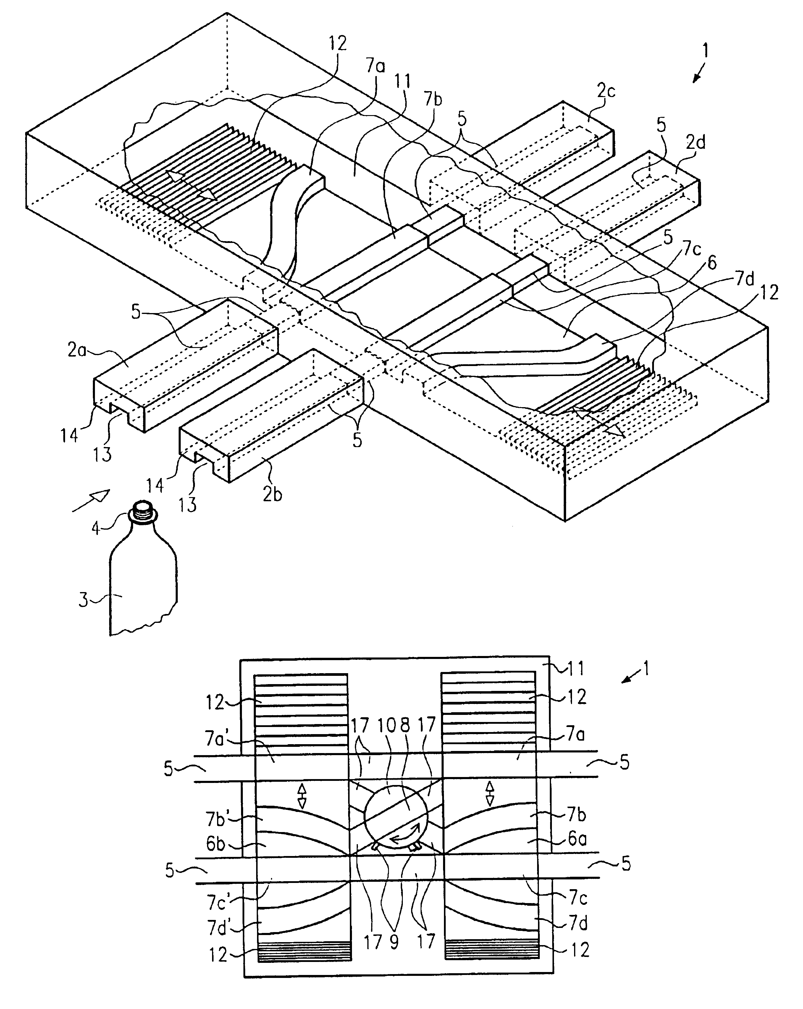
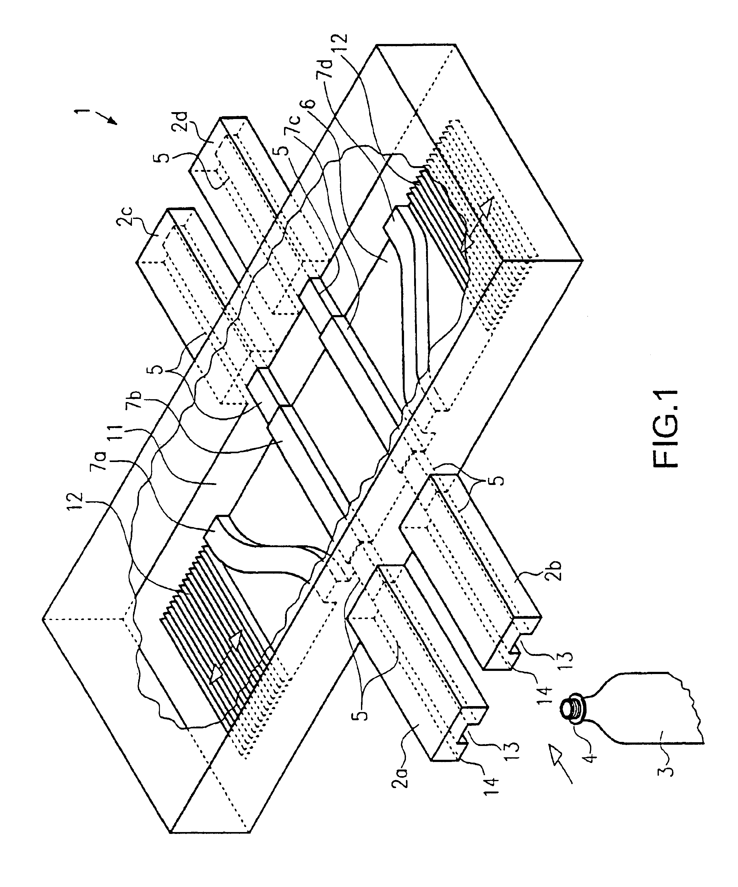
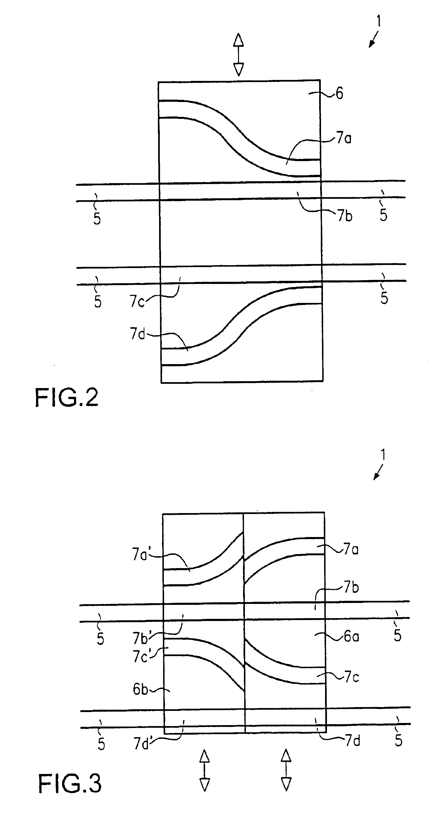
In FIG. 1, the switching device with reference numeral 1 is drawn. In the switching device 1. Air conveyors 2a and 2b with fixed conveyor track sections 5 lead to the switching device 1. The pneumatic conveyors have a channel-like designed head area 13, in which the head of a bottle 3, which presents a support ring, can move, as well as a pressurized air area 14, in which air is pumped by a pump which is not shown; from there the air flows out through small openings into the direction of conveyance, and thus it moves the bottle 3. In the switching device 1, a shifting device 6 is provided, which here is represented substantially in the shape of a plate. The shifting device 6 is provided, or attached in a moveable manner, at the bottom side of the switching device 1. On the shifting device 6, conveyor track sections 7a, 7b, 7c and 7d are shown, which can be moved jointly with the shifting device 6. The conveyor track sections 7a-7d are accessible from below, and they are open downwar...


PUM


Abstract

The invention relates to a switching device for air conveyors for bottles, preforms or similar parts, which can be transported, suspended by their neck in the pneumatic conveyor, where the pneumatic conveyor presents fixed conveyor track sections. The switching device is characterized by the fact that at least one shifting device, which is shiftable with respect to the fixed conveyor track sections, is provided with at least one conveyor track section.

Description

FIELD OF THE INVENTIONThe invention relates to a switching device for pneumatic conveyor by means of which, in particular, plastic bottles can be transported, suspended by their neck, where the air conveyor presents fixed conveyor track sections.BACKGROUND OF THE INVENTIONSuch air conveyors are used for the transport of PET bottles. It may be necessary to change the path which a bottle takes on the way from or to different processing and work stations for bottles.For this purpose a rotating table switch is known from EP 0 649 804. In the case of this switch, a rotating table is provided with three tracks, where, depending on the position of the rotating table, the bottle can move from the incoming into the opposite conveyor tracks, or a bottle can be transferred from one conveyor track to the other, diagonally opposite, conveyor track.The drawback in this context is that, independently of the path which a bottle should take, the bottle always must pass through a curved track, result...

Claims


Application Information

Patent Timeline
IPC IPC(8): B65G51/00B65G51/03B65G47/64
CPCB65G47/642B65G51/035B65G2201/0244
Inventor DRAGON, CHRISTOPHSEIDL, ANDREAS
Owner KRONES AG
Why Eureka
Eureka Blog
Learn More