
Drift pin cap and method of using same

a technology of drift pins and spherical pins, which is applied in the direction of rail fasteners, manufacturing tools, and ways, can solve the problems of affecting the safety of operators, and causing thousands of man-hours lost every year, so as to prevent damage to tools, easy to use, and quick and easy to apply

Inactive Publication Date: 2005-02-15
HUMPHREY JOHN +1
View PDF14 Cites 3 Cited by
  • Summary
  • Abstract
  • Description
  • Claims
  • Application Information

AI Technical Summary

Benefits of technology

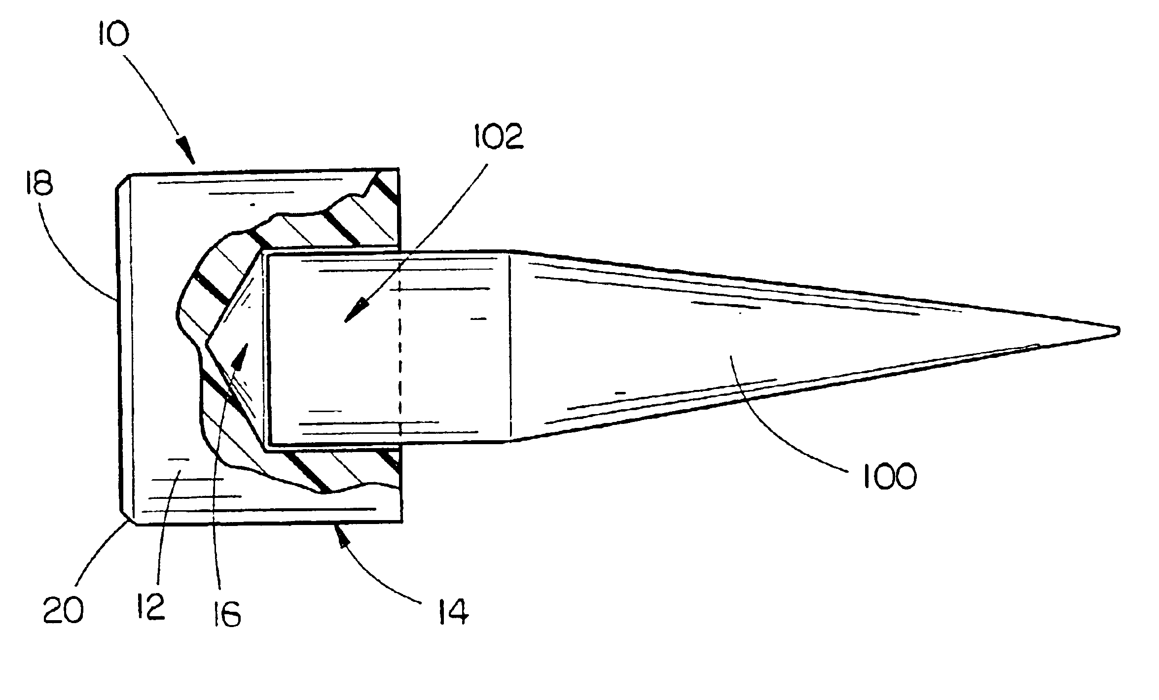
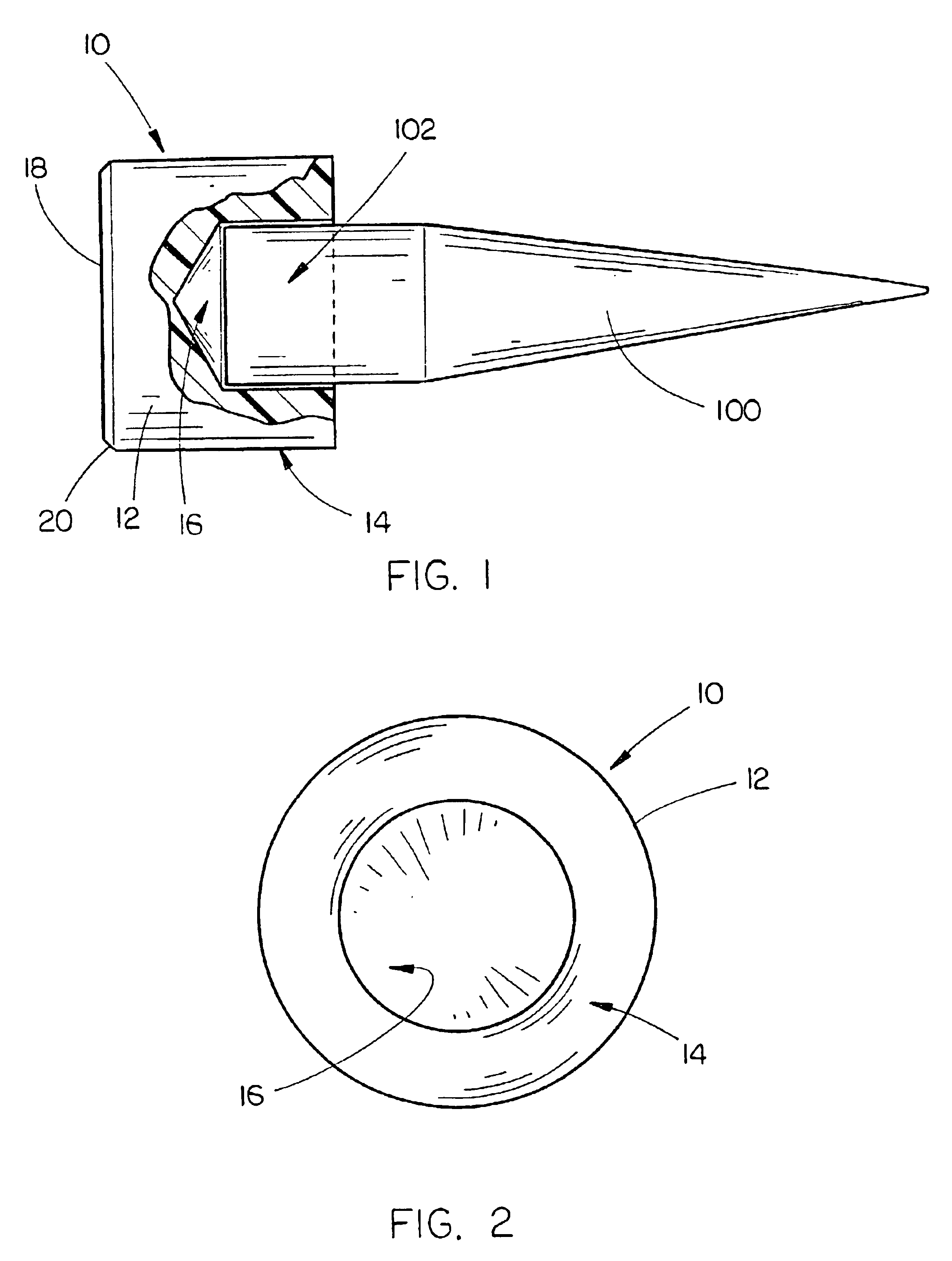
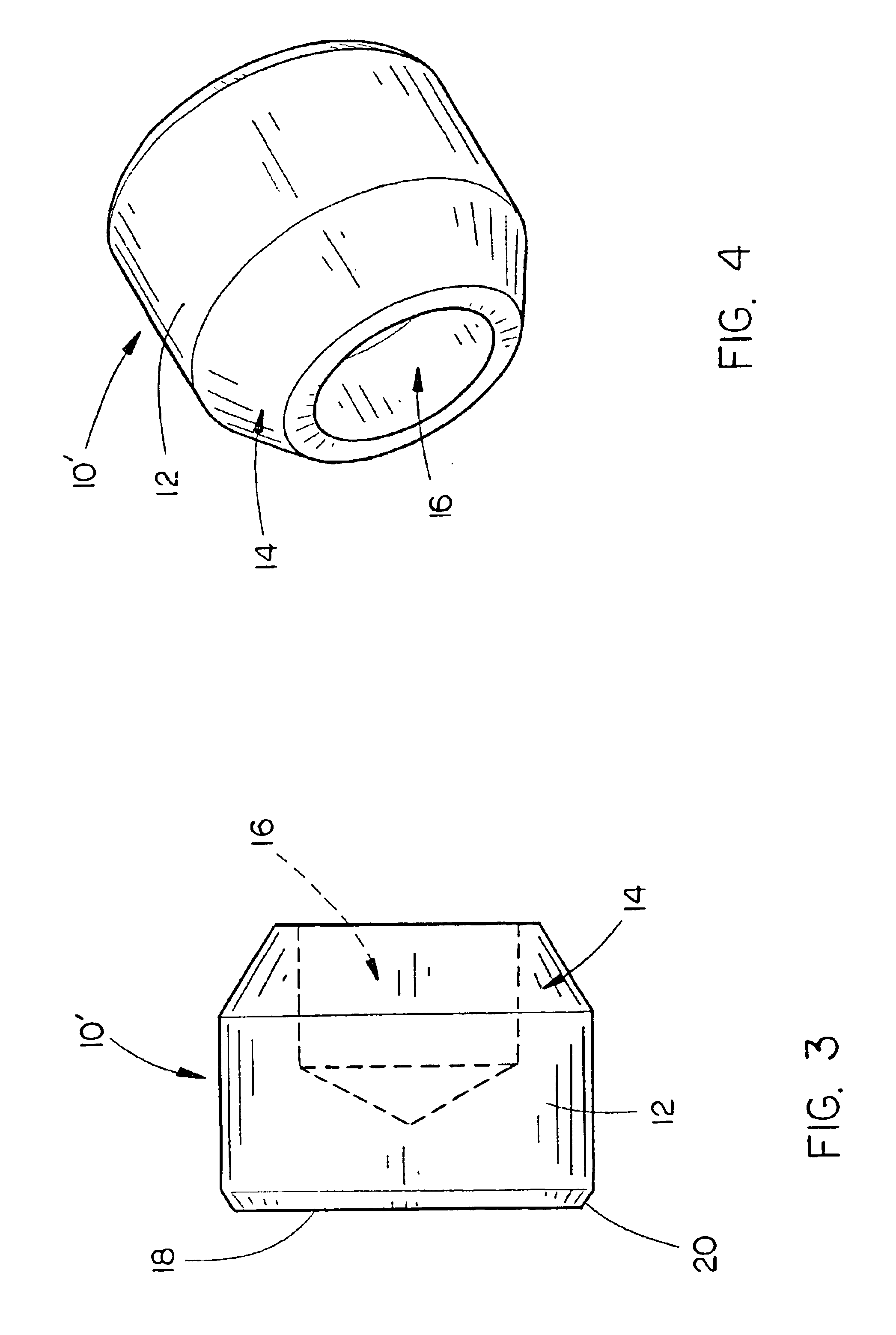
The present invention provides a combination of an elongated tool having a striking end and a tapered insertion end and a drift pin cap. The drift pin cap includes a cap body having an upper end, a lower end and at least one side wall extending between and connecting the upper end and the lower end. A drift pin receiving cavity is formed in the lower end of the cap body which extends upwards towards the upper end within the cap body, the pin receiving cavity having a diameter smaller than a diameter of the cap body. The pin receiving cavity is operative to fit over and be retained on the striking end of the tool such that when the tool is impacted by a driving device, the drift pin cap is interposed between the tool and the driving device to prevent damage to the tool.
The method of using the drift pin cap in connection with the drift pin includes the steps of providing an elongated drift pin having a striking end and a tapered insertion end and providing a drift pin cap including a cap body having an upper end, a lower end and at least one side wall extending between and connecting the upper end and the lower end and a drift pin receiving cavity formed in the lower end of the cap body and extending upwards towards the upper end within the cap body, the pin receiving cavity having a diameter smaller than a diameter of the cap body. The drift pin cap is placed over the striking end of the elongated drift pin with the striking end extending into the pin receiving cavity and being retained therein and the insertion end of the elongated drift pin is placed into a hole to be aligned with another hole. The elongated drift pin is driven into the hole by impact of a driving device with the drift pin cap mounted on the elongated drift pin and splaying of and emission of shrapnel from the elongated drift pin is prevented via the drift pin cap.
It is clear that the features of this invention combine to form an easily used and extremely durable and efficient drift pin cap and method of using same. The drift pin cap is quickly and easily applied to any different drift pin and in fact may be used in connection with many different typed of devices such as stakes, spikes, dowels, chisels, wedges or the like which are to be driven into a plurality of substrates such as dirt, concrete, gravel, or like substrates. Furthermore, the polyethylene component of the present invention is found to be superior to other materials used in the industry and in fact has not been used in this manner or for this purpose. It has been found, however, that it is particularly well-suited for uses described by this invention. Finally, the prevention of splaying of and emission of shrapnel from the elongated drift pin has not been accomplished by the prior art, yet the present invention not only achieves this goal, but provides a safe and easily used apparatus and method by which to do so. It is thus seen that the present invention provides a substantial improvement over the prior art.

Problems solved by technology

Increasing demand for rail transport requires the construction of new track and due to the constant wear and tear on the track, replacement of track sections is often necessary.
One of the major problems in the industry of driving drift pins are the injuries operators incur due to the impact of the driving device onto the drift pin and the subsequent shrapnel that is dislodged.
Thousands of man-hours are lost every year due to such injuries.
In the past, the operator would impact the drift pin with the driving device such as a sledge hammer and the metal of the drift pin would very often become dislodged at high velocity and impact the operator resulting in injuries and the inevitable missing of work.
However, the prior art was problematic in that the rubber caps would disintegrate upon impact and the result would be the same metal shrapnel as before.
The metal caps were even more dangerous as they tended to become deformed upon impact and the metal from the cap could, itself, become shrapnel resulting in injuries to the operator.
Another problem encountered with the prior art is that the striking ends of the drift pins often become splayed or deformed after extended use due to the repeated impact of the driving device onto the striking end.
The resulting damage to the drift pin can eventually render the pin unusable and thus requires replacement of the drift pin.

Method used


Image

  • Drift pin cap and method of using same
  • Drift pin cap and method of using same
  • Drift pin cap and method of using same

Examples


Embodiment Construction

The drift pin cap 10 of the present invention is best shown in FIGS. 1 and 2 as including a generally cylindrical cap body 12 having a height of approximately two to three inches (2″ to 3″) and an outer diameter of approximately two and one-half inches (2½″). In the preferred embodiment the drift pin cap 10 would be constructed of UHMW polyethylene (“UHMW”). UHMW is a lightweight and long wearing polyethylene material that is ideal for this particular application and although the friction-reducing properties of the material have been known, the use of the material in the apparatus and method of the present invention has not been taught or suggested to the inventor's knowledge. The UHMW material has additional properties which lend themselves to use in the present invention, such as it being relatively easy to work with, i.e. requires no special handling techniques, and can be manufactured to meet the shapes and sizes which are preferred in the present invention. Ultra High Molecular...


PUM

PropertyMeasurementUnit
heightaaaaaaaaaa
depthaaaaaaaaaa
heightaaaaaaaaaa

Abstract

In combination, an elongated tool having a striking end and a tapered insertion end and a drift pin cap. The drift pin cap includes a cap body having an upper end, a lower end and at least one side wall extending between and connecting the upper end and the lower end. A drift pin receiving cavity is formed in the lower end of the cap body which extends upwards towards the upper end within the cap body, the pin receiving cavity having a diameter smaller than a diameter of the cap body. The pin receiving cavity is operative to fit over and be retained on the striking end of the tool such that when the tool is impacted by a driving device, the drift pin cap is interposed between the tool and the driving device to prevent damage to the tool yet still permit driving of the tool.

Description

BACKGROUND OF THE INVENTION1. Technical FieldThe present invention is directed to devices and methods associated with the striking and driving of drift pins, stakes, rods, or the like and, more particularly, to a drift pin cap and method of using same including a hardened plastic cap having a drift pin insertion end, the end having a pin receiving cavity, and a striking end that is generally flat whereby a hammer or driving device may impact the drift pin cap without damaging the drift pin and allowing for more efficient driving of the drift pin into the joint bars thereby aligning the rail holes and track.2. Description of the Prior ArtThere are hundreds of thousands of miles of railroad track across the United States and throughout the world, and new construction and maintenance of railroad tracks is an ongoing concern. Increasing demand for rail transport requires the construction of new track and due to the constant wear and tear on the track, replacement of track sections is of...

Claims


Application Information

Patent Timeline
Patent Type & Authority Patents(United States)
IPC IPC(8): E01B29/00E01B29/46
CPCE01B29/46Y10T29/5393
Inventor HUMPHREY, JOHNWIESER, DEAN
Owner HUMPHREY JOHN
Learn More