Protection member for a mesh cable tray, and a tray including said member

Inactive Publication Date: 2005-02-15
LEGRAND ZIBIDO SAN GIACOMO
View PDF8 Cites 70 Cited by
  • Summary
  • Abstract
  • Description
  • Claims
  • Application Information

AI Technical Summary

Benefits of technology

This solution provides a cable tray which has a conventional basic structure on which auxiliary protection members are subsequently fitted in the regions of the above-mentioned nodes, which do not bring about changes in the structure of the tray and c

Problems solved by technology

This solution provides a cable tray which has a conventional basic structure on which auxiliary protection members are subsequently fitted in the regions of the above-mentioned nod

Method used


Image

  • Protection member for a mesh cable tray, and a tray including said member
  • Protection member for a mesh cable tray, and a tray including said member
  • Protection member for a mesh cable tray, and a tray including said member

Examples


Embodiment Construction

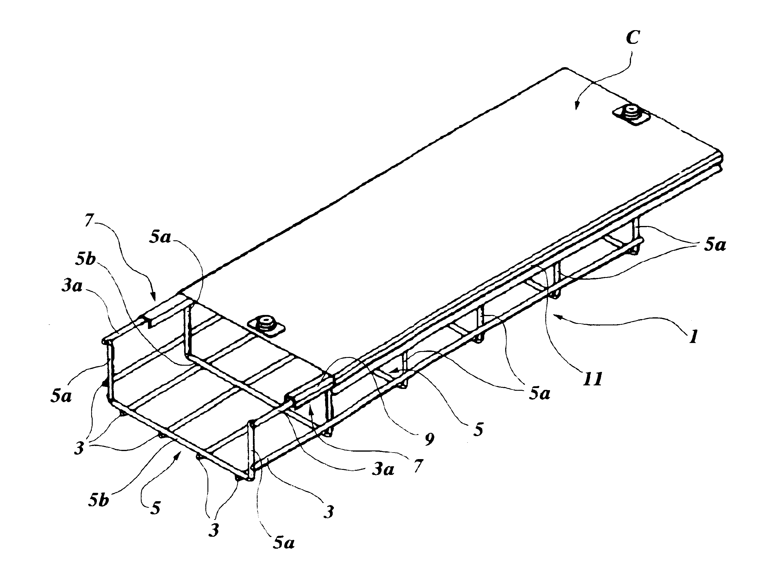
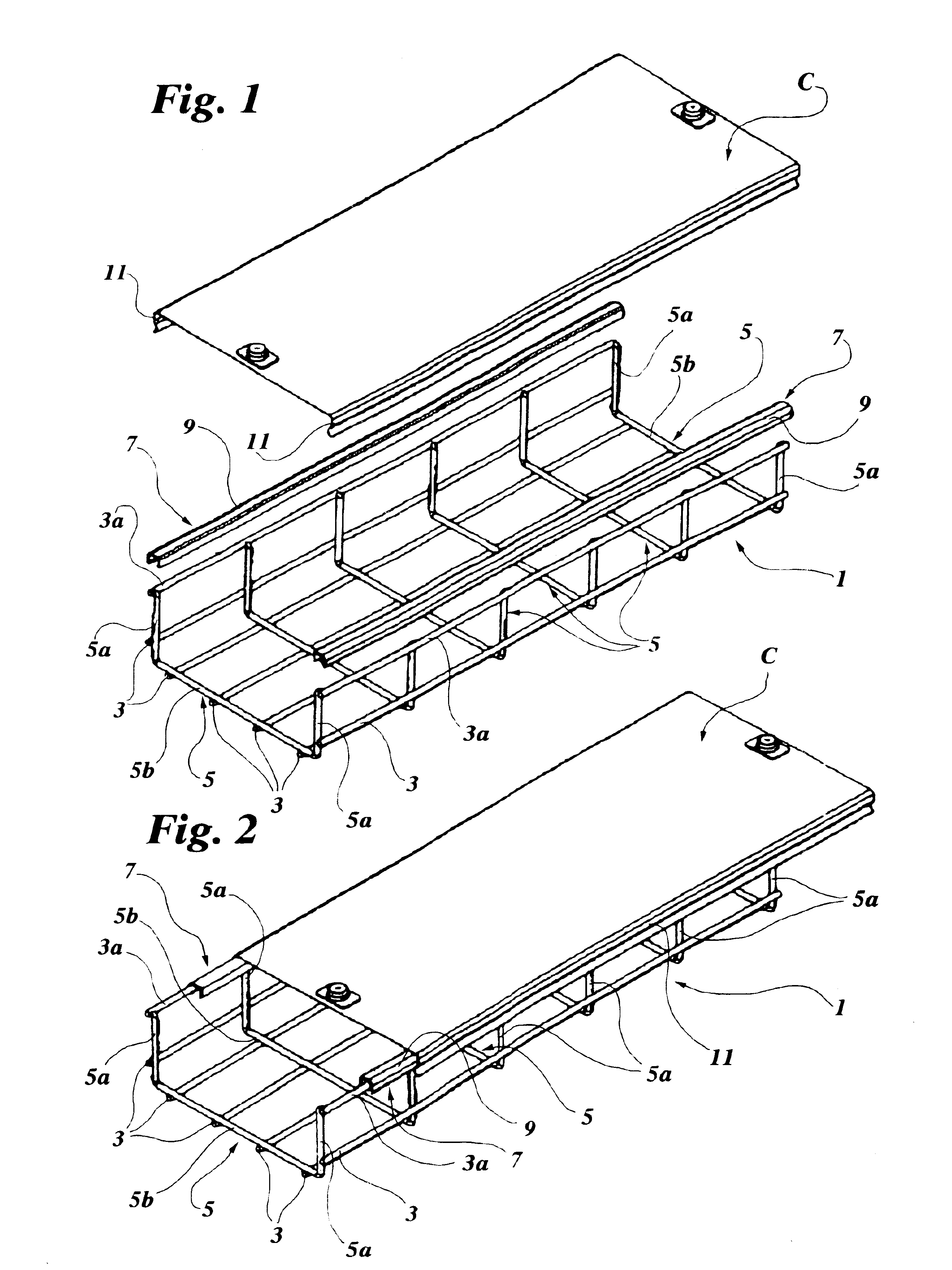
With initial reference to FIGS. 1 and 2, a cable tray 1 of the type generally known as a “mesh” tray comprises a series of longitudinal metal wires 3, 3a and a series of transverse metal wires 5, connected to one another, for example, by electrical welding at nodes to form a grid.

Each of the transverse wires 5 includes a normally straight base portion 5b from which a pair of parallel arms 5a extend transversely relative to the base portion 5b so that each transverse wire 5 is generally U-shaped. The longitudinal wires disposed on the outer sides of the free ends of the parallel arms 5a of the transverse wires 5 are referred to below as “longitudinal edge wires”, and are indicated 3a in the drawings.

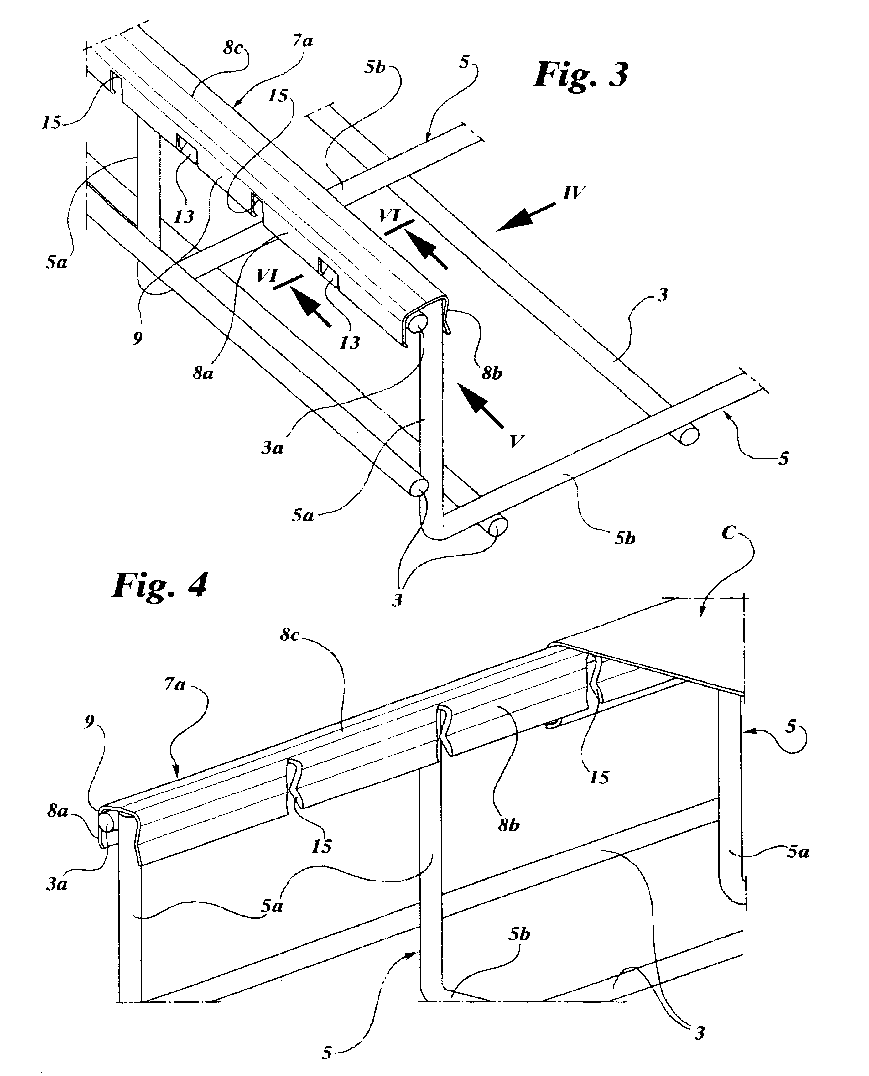
In the region of the longitudinal edge wires 3a, the tray 1 has a pair of channel-shaped, profiled protection elements 7 of uniform cross-section, each of which may have a length equal to one section of cable tray. The elements 7 primarily perform the function of covering the free ends of...


PUM


Abstract

A mesh cable tray comprises a series of longitudinal wires and a series of transverse wires connected to one another at nodes to form a grid, in which each transverse wire includes a base portion from which two parallel arms extend transversely relative to the base portion so that each transverse wire is generally U-shaped. The series of longitudinal wires comprises a pair of longitudinal edge wires which are disposed beside free ends of the parallel arms of the U-shaped transverse wires. The tray has protection members arranged in the regions of the nodes at which the longitudinal edge wires and the parallel arms of the U-shaped transverse wires intersect, in order to cover the free ends of the parallel arms.

Description

FIELD OF THE INVENTIONThe present invention relates to cable trays comprising a series of longitudinal wires and a series of transverse wires, connected to one another at nodes to form a grid, in which each transverse wire includes a base portion from which two parallel arms extend transversely relative to the base portion, so that each transverse wire is generally U-shaped, the series of longitudinal wires comprising a pair of longitudinal edge wires which are disposed beside free ends of the parallel arms of the U-shaped transverse wires.BACKGROUND OF THE INVENTIONIn cable trays of the type defined above, the free ends of the parallel arms of the U-shaped transverse wires are generally trimmed in a plane transverse their general axes so that they have circular sharp edges. Owing to the presence of these sharp edges, the insulating covering of the electrical cables to be disposed in the tray may be damaged during their insertion in the tray and the operators handling the cables of ...

Claims


Application Information

Patent Timeline
IPC IPC(8): H02G3/04
CPCH02G3/0443H02G3/0418
Inventor SPAGNOLI, GIAN PIEROFINCO, ALAN
Owner LEGRAND ZIBIDO SAN GIACOMO
Why Eureka
Try Eureka