Panoramic mirror and system for producing enhanced panoramic images

a technology of enhanced panoramic images and panoramic mirrors, applied in the field of panoramic imaging, can solve the problems of convergent rays of light that make up the reflected image, not providing optimal imaging or resolution, and large amounts of optical distortion in the resulting image, and achieve the effect of improving the usable resolution of the panoramic mirror

Inactive Publication Date: 2005-02-15
360AI SOLUTIONS LLC
View PDF25 Cites 85 Cited by
  • Summary
  • Abstract
  • Description
  • Claims
  • Application Information

AI Technical Summary

Benefits of technology

The present invention improves the usable resolution of panoramic mirrors.
A further aspect of the present invention is to provide a system for providing enhanced panoramic images comprising a mirror, a means for mounting the mirror on an axis, and a camera with a lens. The mirror includes a convex reflective surface symmetric about the axis, and the surface forms a first angle C with respect to a first plane perpendicular to the axis at a point of intersection between the axis and the mirror, the first angle C being determined by a lower limit of a controlled vertical field of view. The camera is positioned so that the lens is substantially aligned with the axis.
Another aspect of the present invention is to provide a system for providing enhanced panoramic images comprising a mirror, a rod positioned on an axis, a means for mounting the mirror on an axis, and a camera with a lens. The mirror includes a convex reflective surface symmetric about the axis, and the surface forms a first angle E with respect to a first plane perpendicular to the axis at a point of intersection between the rod and the mirror, the first angle E being determined by a lower limit of a controlled vertical field of view. The camera is positioned so that the lens is substantially aligned with the axis.
A further aspect of the present invention is to provide a method of providing enhanced panoramic images. The method includes the step of optimizing a resolution of a mirror by selecting the resolution based upon controlling at least one parameter selected from: a shape of the mirror, an upper limit of a controlled vertical field of view, a lower limit of a controlled vertical field of view, an upper limit of a desired vertical field of view, a lower limit of a desired vertical field of view, and a vertical pixel radius.
Another aspect of the present invention is to provide a method of providing enhanced panoramic images. The method includes the steps of providing a camera with a mirror, wherein the mirror includes a convex reflective surface symmetric about an axis, obtaining a raw panoramic image using the camera and the mirror, the image having pixel representations comprising a vertical pixel radius, a horizontal pixel circumference at an upper limit of a desired vertical field of view, and a horizontal pixel circumference at a lower limit of a desired vertical field of view, and optimizing a resolution of the mirror by modifying the mirror to obtain desired pixel representations.

Problems solved by technology

A drawback to this is the fact that a typical 180-degree lens can cause substantial amounts of optical distortion in the resulting image.
Spherical mirrors have constant curvatures and are easy to manufacture, but do not provide optimal imaging or resolution.
A major drawback to this system lies in the fact that the rays of light that make up the reflected image converge at the focal point of the reflector.
As a result, positioning of the sensor relative to the reflecting surface is critical, and even a slight disturbance of the mirror will impair the quality of the image.
Another disadvantage is that the use of a perspective-projections model inherently requires that, as the distance between the sensor and the mirror increases, the cross-section of the mirror must increase.
This causes complications to arise with respect to the design of the image sensor optics.
A disadvantage of this system is that many of the light rays are not orthographically reflected by the parabolic mirror.
However, when this system is combined with a camera lens, the combination of the lens and the equi-angular mirror is no longer a projective device, and each pixel does not span exactly the same angle.
However, this system does not take into account the fact that there may be certain areas of the resulting panoramic image that a viewer may have no desire to see.
Therefore, some of the superior image resolution resources of the mirror are wasted on non-usable portions of the image.

Method used


Image

  • Panoramic mirror and system for producing enhanced panoramic images
  • Panoramic mirror and system for producing enhanced panoramic images
  • Panoramic mirror and system for producing enhanced panoramic images

Examples


Embodiment Construction

The present invention improves the usable resolution of panoramic mirrors and provides enhanced panoramic images.

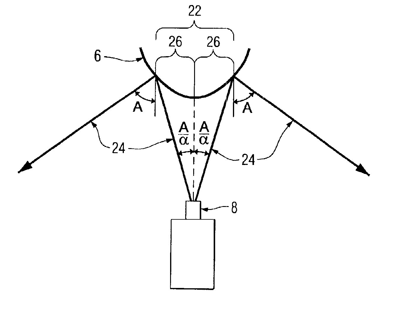
As used herein, the term “panoramic images” means wide-angle images taken from a field of view of from about 60° to 360°, typically from about 90° to 360°. Preferably, the panoramic visual images comprise a field of view from about 180° to 360°. In a particular embodiment, the field of view is up to 360° in a principal axis, which is often oriented to provide a 360° horizontal field of view. In this embodiment, a secondary axis may be defined, e.g., a vertical field of view. The vertical field of view may be defined with respect to the optical axis of a camera lens, with the optical axis representing 0°. Such a vertical field of view may range from 0.1° to 180°, for example, from 1° to 160°. In accordance with the present invention, the vertical field of view is controlled in order to maximize the resolution of the portion of the panoramic image that the viewer is most in...


PUM


Abstract

The present invention relates to providing enhanced panoramic images with an improved panoramic mirror. A panoramic mirror is provided with a controlled vertical field of view. The controlled vertical field of view improves the resolution of a viewable panoramic image by eliminating portions of unwanted images from the viewable panoramic image.

Description

FIELD OF THE INVENTIONThe present invention relates to panoramic imaging, and more particularly relates to an improved panoramic mirror for providing enhanced panoramic images.BACKGROUND INFORMATIONRecent work has shown the benefits of panoramic imaging, which is able to capture a large azimuth view with a significant elevation angle. If instead of providing a small conic section of a view, a camera could capture an entire half-sphere or more at once, several advantages could be realized. Specifically, if the entire environment is visible at the same time, it is not necessary to move the camera to fixate on an object of interest or to perform exploratory camera movements. Additionally, this means that it is not necessary to stitch multiple, individual images together to form a panoramic image. This also means that the same panoramic image or panoramic video can be supplied to multiple viewers, and each viewer can view a different portion of the image or video, independent from the o...

Claims


Application Information

Patent Timeline
Patent Type & Authority Patents(United States)
IPC IPC(8): G02B13/06G02B17/00
CPCG02B13/06G02B13/08G06T3/0062G03B17/565G03B37/06G02B17/08
Inventor HERMAN, HERMANSINGH, SANJIV
Owner 360AI SOLUTIONS LLC
Why Eureka
Try Eureka