
Method and system for transporting packet-switched control traffic in an optical network

Inactive Publication Date: 2005-02-15
FUJITSU LTD
View PDF4 Cites 37 Cited by
  • Summary
  • Abstract
  • Description
  • Claims
  • Application Information

AI Technical Summary

Benefits of technology

The present invention provides an improved method and system for transporting packet-switched control traffic in an optical network that reduce or eliminate at least some of the shortcomings of previous systems and methods. In particular, the invention encapsulates packet-switched traffic within OSI packets in a SONET overhead and communicates the OSI packets through an optical network using standard protocols.
Numerous technical advantages can be gained through various embodiments of the invention. Various embodiments of the invention may exhibit none, some, or all of the following advantages. For example, in one embodiment of the invention, a system is provided that allows packet-switched traffic to be communicated over an optical network. In particular, the packet-switched traffic may be placed into Open Systems Interconnection (OSI) packets, and the OSI packets may be transported between network elements in the optical network. This allows the packet-switched traffic to flow through the optical network.
Another advantage of some embodiments of the invention is that the use of proprietary protocols to transport packet-switched traffic may be reduced or eliminated in the optical network. As a result, network elements from different vendors may be used in the same optical network. Because the network elements may not be required to understand proprietary protocols to transport IP traffic in the optical network, the network elements manufactured by one vendor may be able to communicate more effectively with the network elements of other manufacturers. Because of this, adding or replacing network elements in the optical network may be simpler. The network operator may not need to verify that the element being placed in the network can understand proprietary protocols used by existing network elements to transport IP traffic.
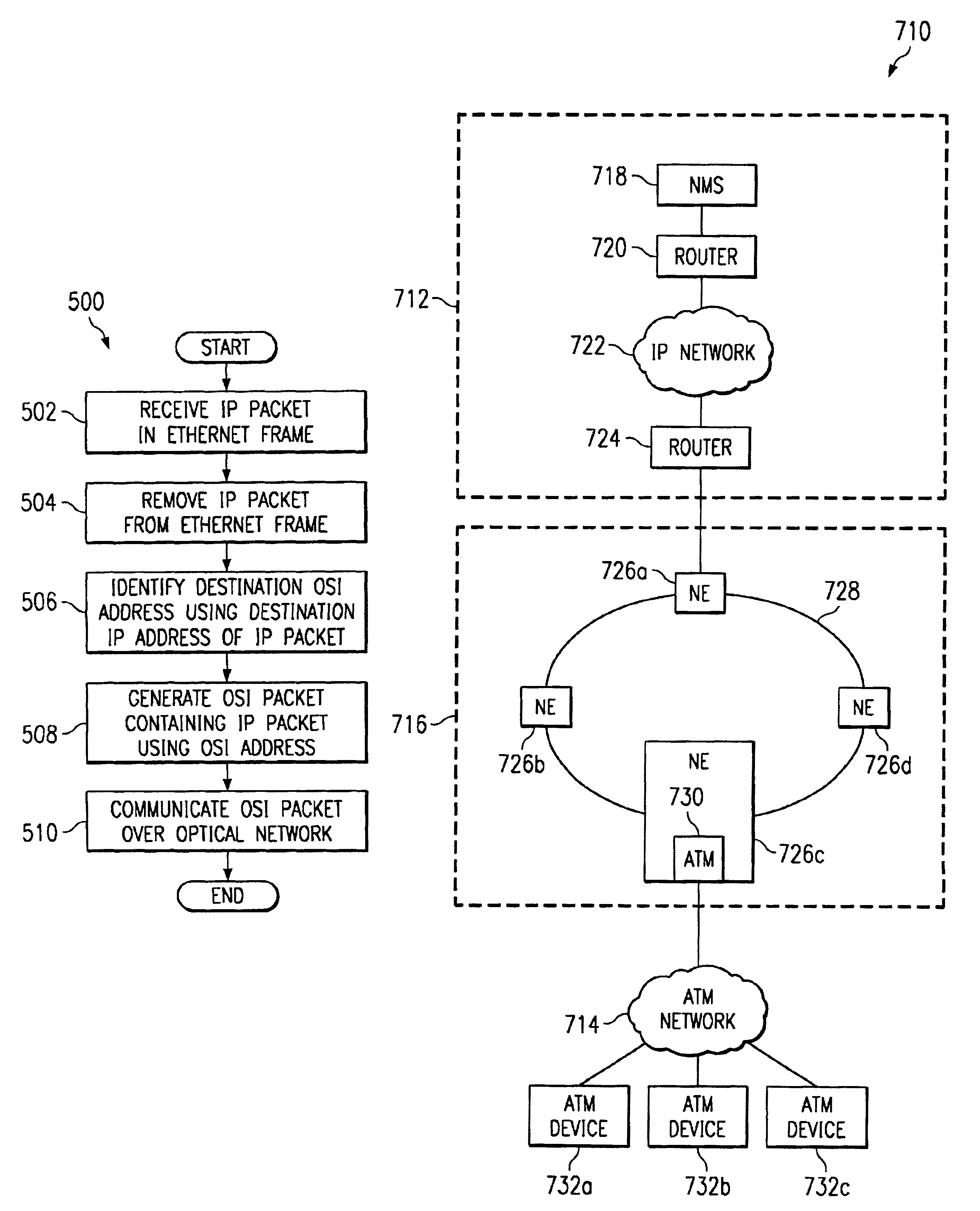
In addition, some embodiments of the invention may be integrated more easily with legacy optical networks. For example, in one embodiment, one network element in the optical network may communicate with a first network, and another network element may communicate with a second network. In this embodiment, the network elements communicating with the first and second networks recognize and process the packet-switched traffic, and the packet-switched traffic is transported transparently across the remaining network elements in OSI packets. The remaining network elements in the optical network may not need to recognize that packet-switched traffic is contained in the OSI packets. As a result, in this embodiment, only two network elements may need to process packet-switched traffic. This helps to reduce the cost of providing this functionality in the optical network by reducing the number of network elements to be upgraded or replaced.

Problems solved by technology

As a result, it is often difficult for a packet-switched network to communicate packet-switched traffic to another network over an optical network.
The different protocols make communication of packet-switched traffic through the optical network difficult at best.
Transporting the packet-switched traffic through the optical network may not be possible, which prevents other networks from communicating through the optical network.
A problem with these approaches is that network elements from different vendors often could not be used in the same optical network.
Because the prior approaches often use proprietary solutions, the network elements manufactured by one vendor may not be able to communicate effectively with the network elements of other manufacturers.
As a result, adding or replacing network elements in the optical network is often difficult.
If the new element cannot, the network operator often could not use the new element in the network.
This limits the available network elements that may be placed in the network.
Another problem with these approaches is that adding the ability to transport packet-switched traffic typically requires upgrading or replacing many of the network elements in legacy optical networks.
As a result, the cost of providing this functionality in the optical network increases.

Method used


Image

  • Method and system for transporting packet-switched control traffic in an optical network
  • Method and system for transporting packet-switched control traffic in an optical network
  • Method and system for transporting packet-switched control traffic in an optical network

Examples


Embodiment Construction

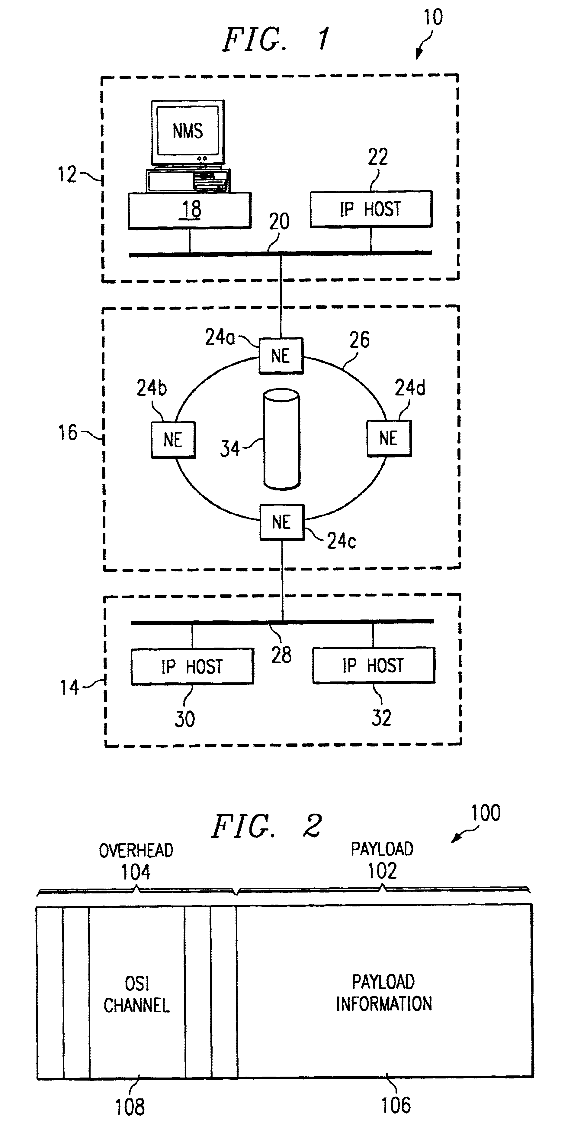
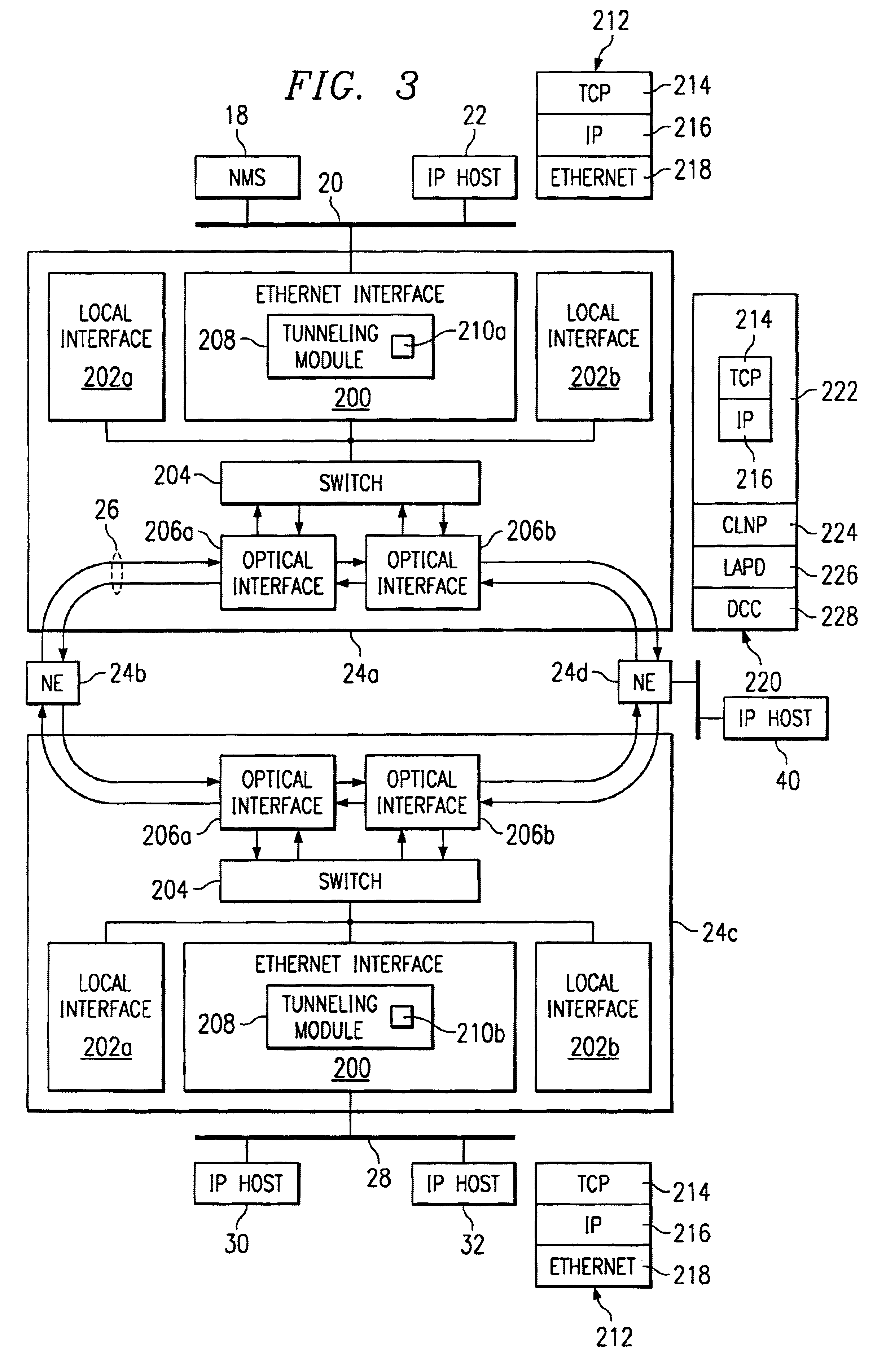
FIG. 1 is a block diagram illustrating a communications system 10 for transporting packet-switched traffic in an optical network 16 in accordance with one embodiment of the invention. In the illustrated embodiment, system 10 includes a first packet-switched network 12, a second packet-switched network 14, and an optical network 16. Other embodiments of system 10 may be used without departing from the scope of the present invention.

In one aspect of operation, optical network 16 includes a plurality of network elements (NE) 24 arranged in a ring. In one embodiment, optical network 16 comprises a Synchronous Optical Network (SONET) ring. In this embodiment, network elements 24 communicate using the SONET protocol suite, which includes the Open Systems Interconnection (OSI) protocol suite, and network elements 24 exchange SONET frames over communication links 26. First packet-switched network 12 and second packet-switched network 14 may use a packet-switched protocol, such as the Intern...


PUM


Abstract

A method for transporting packet-switched control traffic in an optical network includes receiving a packet-switched datagram comprising a destination address. The method also includes identifying a destination Open Systems Interconnection (OSI) address of a destination network element in the optical network based on the destination address of the datagram. In addition, the method includes generating an OSI packet comprising the datagram and the destination OSI address, and transmitting the OSI packet on the optical network in an OSI channel of a Synchronous Optical Network (SONET) frame.

Description

TECHNICAL FIELD OF THE INVENTIONThis invention relates generally to optical communications systems, and more particularly to a method and system for transporting packet-switched control traffic in an optical network.BACKGROUND OF THE INVENTIONCommunications systems are rapidly expanding in order to increase the amount of information that may be transported through those systems. These communications systems often include different types of networking equipment, such as optical networking equipment and packet-switched communications equipment. Optical networks, such as a Synchronous Optical Network (SONET), often include multiple network elements arranged in a ring. Each network element typically communicates directly with two other network elements in the ring, one network element in each direction of the ring. When one network element needs to communicate information to another network element, the first network element communicates the information to the second network element thr...

Claims


Application Information

Patent Timeline
IPC IPC(8): H04J3/16H04L29/06H04Q11/04
CPCH04J3/1617H04L69/168H04L69/16H04J2203/0083
Inventor DUNSMORE, RICHARD J.FONG, MAN W.DUNBAR, LINDA W.
Owner FUJITSU LTD
Learn More