Recording apparatus and coding apparatus

a technology of coding apparatus and recording medium, which is applied in the direction of electronic editing digitised analogue information signals, instruments, television systems, etc., can solve the problems of insufficient video resolution management, difficult management of video attribute of stream recorded on recording medium, and inability to direct access to the position where video resolution is achieved. , to achieve the effect of facilitating the decoding of video stream

Inactive Publication Date: 2005-02-15
PANASONIC CORP
View PDF11 Cites 50 Cited by
  • Summary
  • Abstract
  • Description
  • Claims
  • Application Information

AI Technical Summary

Benefits of technology

According to a seventeenth aspect of the present invention, the coding apparatus of the sixteenth aspect further comprises a packing unit for performing packing to divide the video stream into plural streams corresponding to packs as data units each having a predetermined size, and outputting the stream corresponding to each pack as pack data; and the packing unit performs the packing such that a position in the video stream, where the video or audio attribute changes, is positioned at the head of the pack. Therefore, when playing the video stream recorded on the recording medium while managing the addresses in pack units, a portion of the stream corresponding to the attribute change point can be accessed quickly.
According to an eighteenth aspect of the present invention, in the coding apparatus of the fifteenth aspect, the video encoder performs coding on each frame in a specific frame group including the specific frame, without referring to the video signal corresponding to frames in a frame group which has been coded previously to the specific frame group. Therefore, the video stream corresponding to the specific frame group can be played randomly. That is, coding of the specific frame group is performed without referring to the video signal of an already processed frame group whose video attribute video resolution) is different from that of the specific frame group. Therefore, when a target frame to be coded is subjected to inter-frame prediction coding, only a frame whose video attribute (video resolution) is identical to that of the target frame is used as a reference frame, whereby decoding of the video stream is facilitated. Further, when the target frame is subjected to inter-frame prediction coding, only a frame whose aspect ratio is identical to that of the target frame is used as a reference frame, whereby the target frame is coded efficiently.
According to a nineteenth aspect of the present invention, in the coding apparatus of the fifteenth aspect, the video attribute detector detects the video resolution of the video signal as a video attribute on the basis of the video signal, and outputs video resolution data indicating the video resolution; and the video encoder forms the frame group, on the basis of the video resolution data, such that a specific frame, whose video resolution is different from that of a frame positioned just before it, is stored as a head frame in the frame group. Therefore, when playing the video stream recorded on the recording medium with each frame group as an access unit, a portion of the video stream where the video resolution changes can be accessed quickly.
According to a twentieth aspect of the present invention, the coding apparatus of the nineteenth aspect further comprises a packing unit for performing packing to divide the video stream into plural streams corresponding to packs as data units each having a predetermined size, and outputting the stream corresponding to each pack as pack data; and the packing unit performs the packing such that a position in the video stream, where the video resolution changes, is positioned at the head of the pack. Therefore, when playing the video stream recorded on the recording medium while managing the addresses in pack units, a portion of the stream corresponding to the resolution change point can be accessed quickly.
According to a twenty-first aspect of the present invention, in the coding apparatus of the fifteenth aspect, the attribute detector detects the aspect ratio of the video signal as the video attribute on the basis of the video signal, and outputs aspect ratio data indicating the aspect ratio; and the video encoder forms the frame group, on the basis of the aspect ratio data, such that a specific frame, whose aspect ratio is different from that of a frame positioned just before it, is stored as a head frame in the frame group. Therefore, when playing the video stream recorded on the recording medium with each frame group as an access unit, a portion of the video stream where the aspect ratio changes can be accessed quickly.
According to a twenty-second aspect of the present invention, the coding apparatus of the twenty-first aspect further comprises a packing unit for performing packing to divide the video stream into plural streams corresponding to packs as data units each having a predetermined size, and outputting the stream corresponding to each pack as pack data; and the packing unit performs the packing such that a position in the video stream, where the aspect ratio changes, is positioned at the head of the pack. Therefore, when playing the video stream recorded on the recording medium while managing the addresses in pack units, a ort-on of the stream corresponding to the aspect ratio change point can be accessed quickly.

Problems solved by technology

In this case, two audio video streams having different attributes are recorded as one VOB, whereby management of the video attribute of the stream recorded on the recording medium becomes difficult.
Further, in the process of playing the audio video stream recorded or the recording medium, since the video stream (coded data) is decoded with the video resolution as a parameter, management of the video resolution as the video attribute is insufficient.
If the change of the video re olution is not posted to the decoder, decoding of the video stream results in failure.
Furthermore, since the recording position of the audio video stream is managed by the address corresponding to each VOBU which is a constituent of the VOB, direct access cannot be made to the position where the video resolution changes, in the stream included in the VOBU.
Therefore, random access to the beginning of the program, based on the change of the video resolution, cannot be performed at high speed.
Therefore, when the video resolution changes, the video resolution varies between the target frame and the reference frame, and the inter-frame predictive coding results in failure.
That is, when the video aspect ratio changes, management of the video attribute of the recorded audio video stream (coded data) becomes difficult.
Further, in the playback process, decoding of the coded data results in failure due to the change of the video aspect ratio.
Moreover, quick access cannot be made to the position where the video aspect ratio changes, in the video stream.
Moreover, in the MPEG coding, when the video aspect ratio changes, a stream adapted to the MPEG-2 standard cannot be generated, or the inter-frame predictive coding results in failure, as in the above-described case where the video resolution changes.

Method used


Image

  • Recording apparatus and coding apparatus
  • Recording apparatus and coding apparatus
  • Recording apparatus and coding apparatus

Examples


embodiment 1

[Embodiment 1]

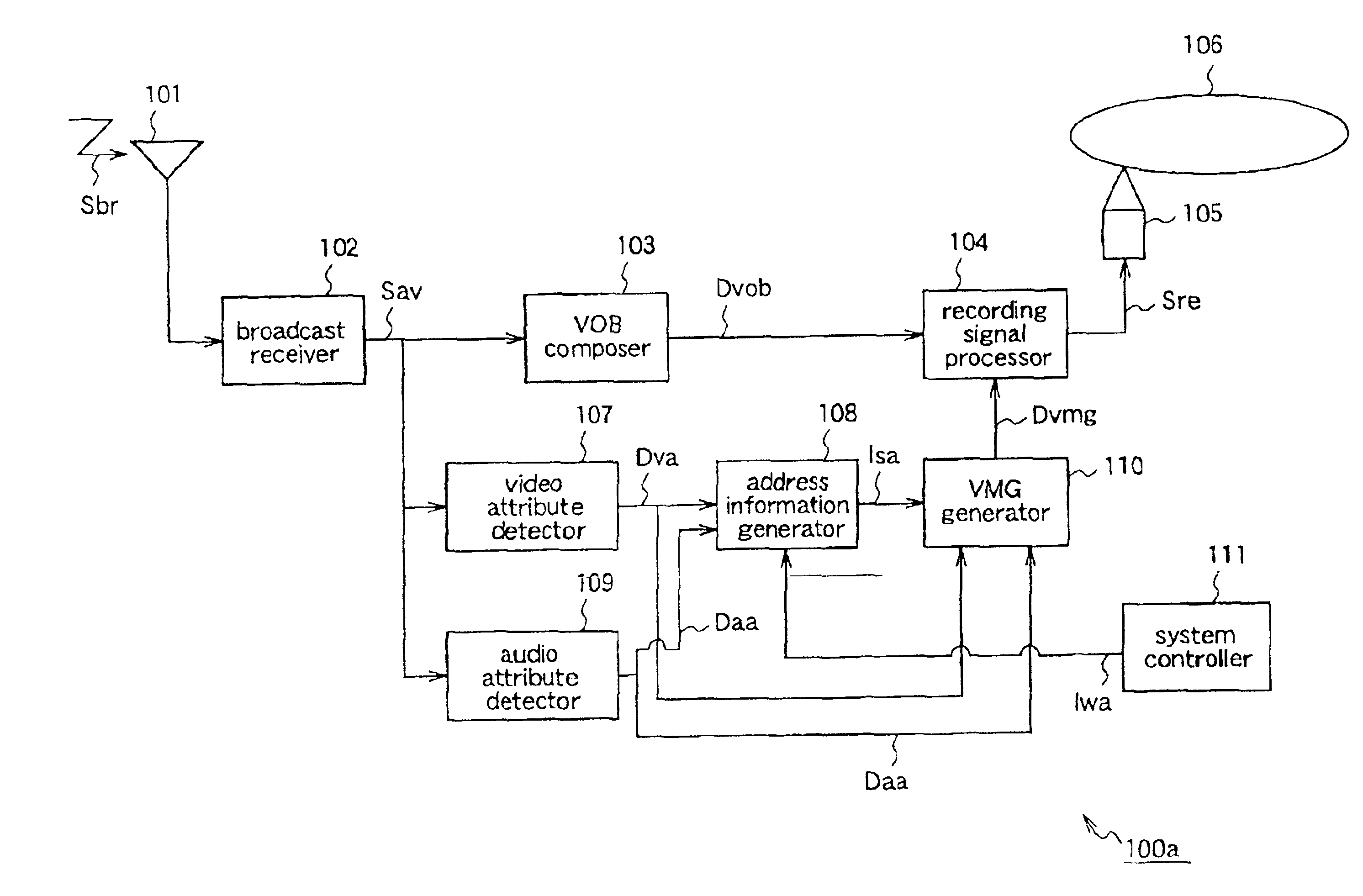
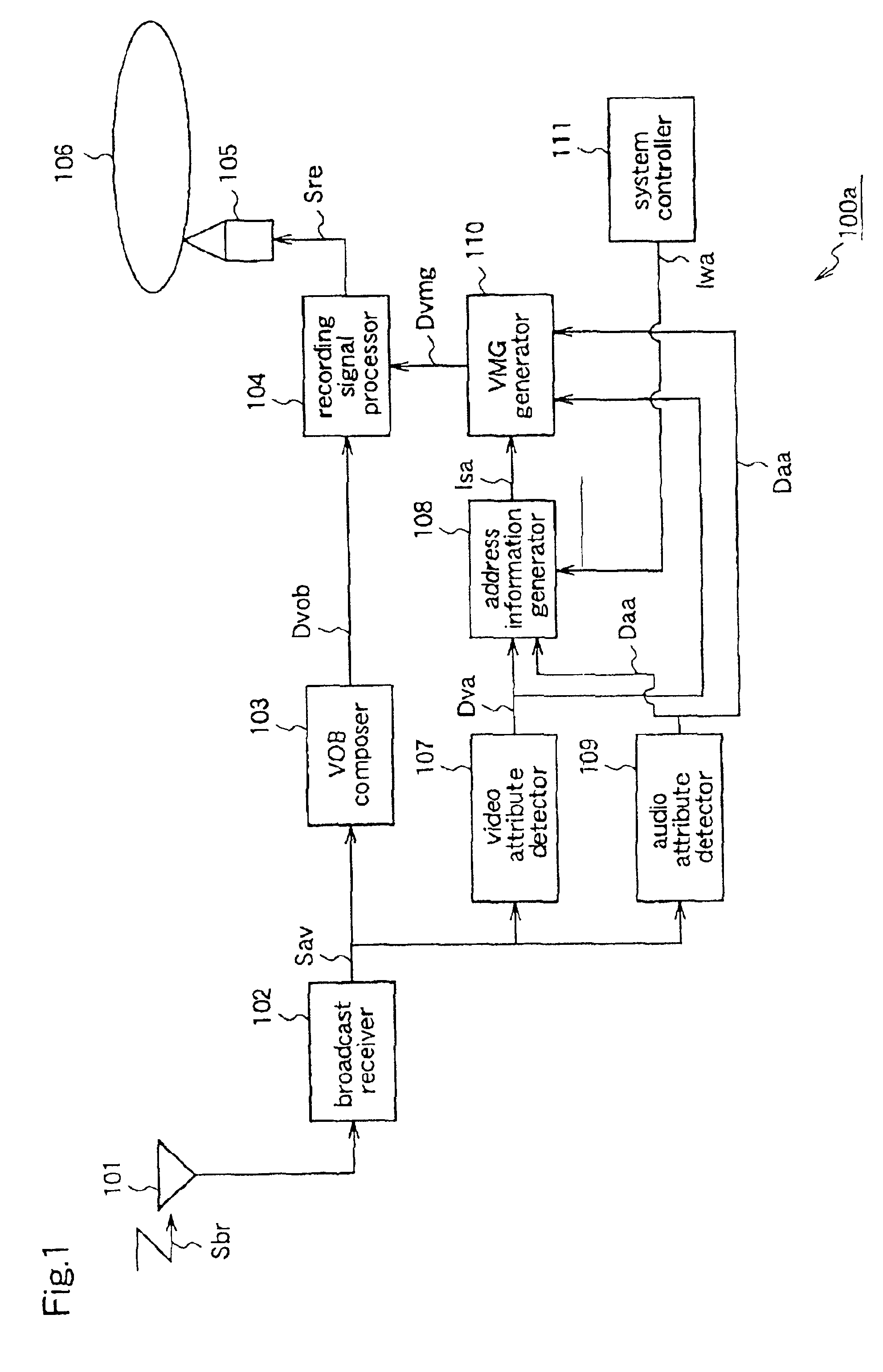
FIG. 1 is a block diagram for explaining a recording apparatus 100a according to a first embodiment of the present invention.

The recording apparatus 10a includes a broadcast receiver 102 and a VOB composer 103. The broadcast receiver receives a digital broadcast signal Sbr, and outputs an audio video stream Sav. The VOB composer 103 converts the audio video stream Sav into recordable data according to a format of a video standard, and outputs VOB data Dvob.

The broadcast receiver 102 has a TS / PS conversion function for converting a transmission format stream (transport stream) into a record format stream (program stream), and the audio video stream Sav outputted from the broadcast receiver 102 is a program stream. Further, a packing unit (not shown) is provided between the broadcast receiver 102 and the VOB composer 103. The packing unit divides the audio video stream Sav into plural streams corresponding to first data units each having a predetermined size (2 Kbyte). T...

embodiment 2

[Embodiment 2]

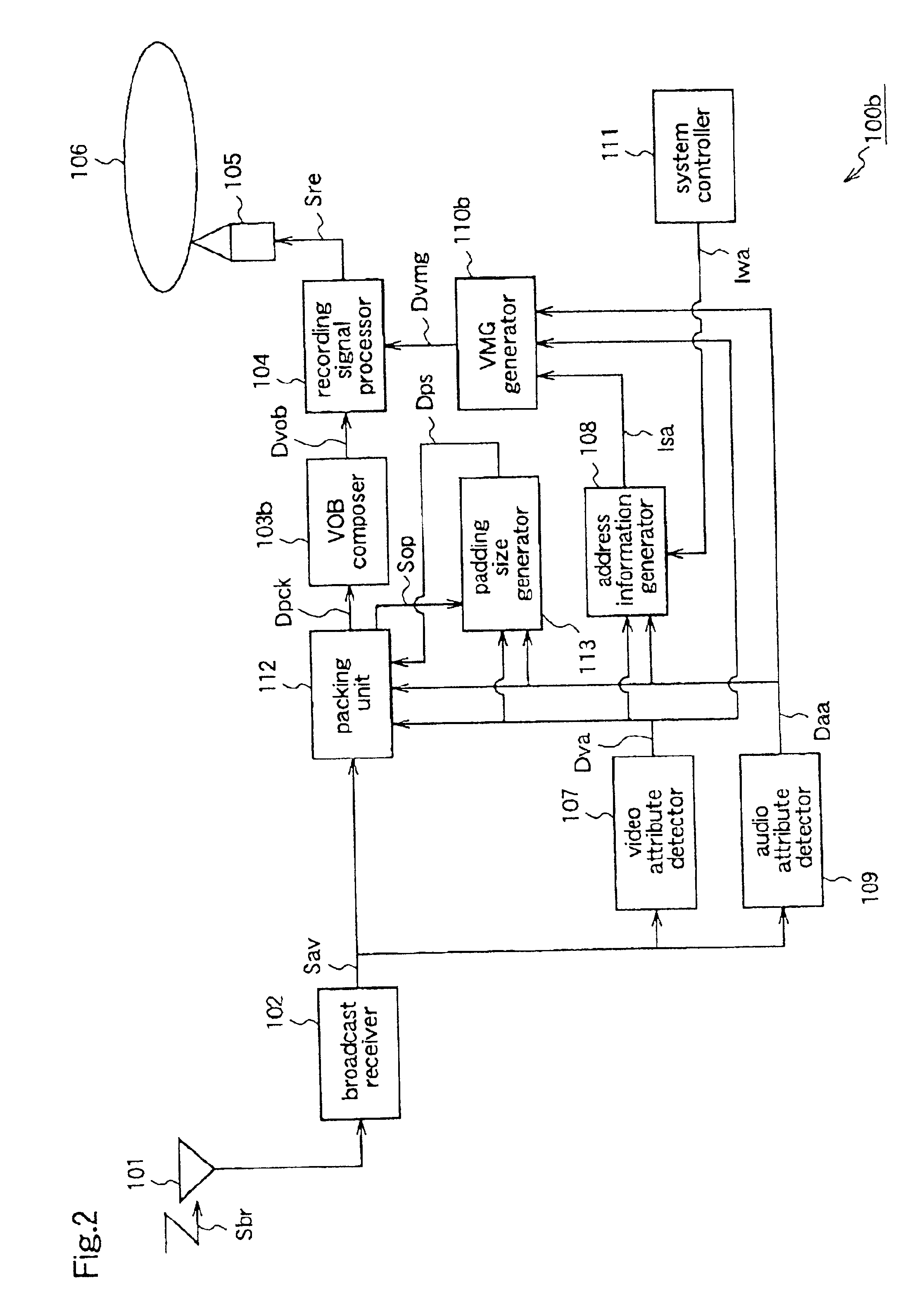
FIG. 2 is a block diagram for explaining a recording apparatus 100b according to a second embodiment of the present invention.

The recording apparatus 100b of this second embodiment includes a packing unit 112 and a padding size generator 113, instead of the packing unit of the first embodiment. The packing unit 112 performs the same packing process as described for the first embodiment. Further, when the audio attribute or the video attribute changes, the packing unit 112 inserts padding data in the pack which is being formed, following the stream just before the attribute change, to prevent the stream before the attribute change and the stream after the attribute change from being stored in one pack. The padding size generator 113 calculates the size of the padding data on the basis of the video attribute data Dva, the audio attribute data Daa, and an internal signal Sop of the packing unit 112, and outputs size information Dps indicating the size to the packing unit ...

embodiment 3

[Embodiment 3]

FIG. 3 is a black diagram for explaining a recording apparatus 100c according to a third embodiment of the present invention.

This recording apparatus 100c includes a VMG generator 110c instead of the address information generator 108 and the VMG generator 110 of the first embodiment. The VMG, generator 110c generates VMG information Dvmg, which is management information for each VOB, on the basis of the video attribute data Dva and the audio attribute data Daa supplied from the attribute detectors 107 and 109, respectively.

The recording apparatus 100c further includes a VOB composer 103c instead of the VOB composer 103 of the first embodiment. When either the audio attribute or the video attribute changes, the VOB composer 103c generates VOB data so that the stream before the attribute change and the stream after the attribute change are separated as different VOB data, on the basis of the video attribute data Dva and the audio attribute data Daa.

Other constituents of ...


PUM

PropertyMeasurementUnit
frame frequencyaaaaaaaaaa
display timeaaaaaaaaaa

Abstract

A recording apparatus includes a detector for detecting a video attribute, a detector for detecting an audio attribute, and an address information generator for generating specific address information which indicates a data write address at the time when the video attribute of the audio attribute changes, on the basis of the outputs from the detectors. The specific address information is written in a recording area of an optical disk, which area corresponds to VMGI constituting management information (VMG information) for each VOB. Therefore, when playing an audio video stream recorded on the optical disk, quick access can be made to the recording position in the stream where the attribute change occurs.

Description

FIELD OF THE INVENTIONThe present invention relates to a recording apparatus and a coding apparatus and, more particularly, to an apparatus for recording an audio video signal on a recording medium, and an apparatus for coding a video signal.BACKGROUND OF THE INVENTIONOn a playback-only DVD (Digital Video Disk), coded data which is obtained by performing compressive coding on an audio video signal corresponding to a specific program or the like, is recorded. This audio video signal includes an audio signal and a video signal, and coded audio data obtained by coding the audio signal and coded video data obtained by coding the video signal are recorded on the DVD as the above-described coded data. Further, the coded audio data and the coded video data are respectively packed. That is, these coded data are divided into plural pieces of data corresponding to first data units each having a predetermined data size (e.g., 2048 bytes).In the following description, the coded audio data corre...

Claims


Application Information

Patent Timeline
Patent Type & Authority Patents(United States)
IPC IPC(8): G11B27/30G11B27/031G11B27/034G11B27/32H04N9/804H04N9/806H04N5/84H04N5/85G11B20/10
CPCG11B27/034G11B27/3027G11B27/329H04N5/91H04N9/8042H04N9/8063H04N5/85G11B2220/2562G11B20/10
Inventor FUKUDA, HIDEKIKONDO, SATOSHI
Owner PANASONIC CORP
Why Eureka
Try Eureka