Work machine management device

a technology for managing devices and work machines, applied in the direction of instruments, analogue processes for specific applications, electric/magnetic computing, etc., can solve the problems of time delay, inability to learn the exact location to which each operator has operated the construction machine, and inability to perform services

Inactive Publication Date: 2005-02-15
KOMATSU LTD
View PDF17 Cites 51 Cited by
  • Summary
  • Abstract
  • Description
  • Claims
  • Application Information

AI Technical Summary

Benefits of technology

According to the eighth invention as described above, information comprising icons is transmitted and received, and therefore communication messages displayed on the display means (the monitoring panel display unit) on the work machine side can be greatly shortened. As a result, communication messages can be displayed on t

Problems solved by technology

Hence, by simply reading the service meter, the extent to which each operator has operated the construction machine cannot be learned.
However, whether or not the service person has actually performed services such as repair, parts exchange, or inspection depends upon the subsequent report made by the service person, and thus a time delay occurs from the actual performance of these services to the administrator learning the results of these services.
Further, due to an error or the like by the service person, services may not actually have been performed, or a report of the service results may be omitted.

Method used


Image

  • Work machine management device
  • Work machine management device
  • Work machine management device

Examples


first embodiment

(First Embodiment)

The first embodiment will be described with reference to FIG. 42. In this first embodiment, the terminal 11 is provided on the side of an administrator who manages a plurality of operators.

FIG. 42 illustrates the display content of a display screen on the terminal 11 display device.

In this first embodiment, a case is envisaged in which the construction machine 31 is driven alternately by three operators and the other construction machine 32 is driven alternately by two operators.

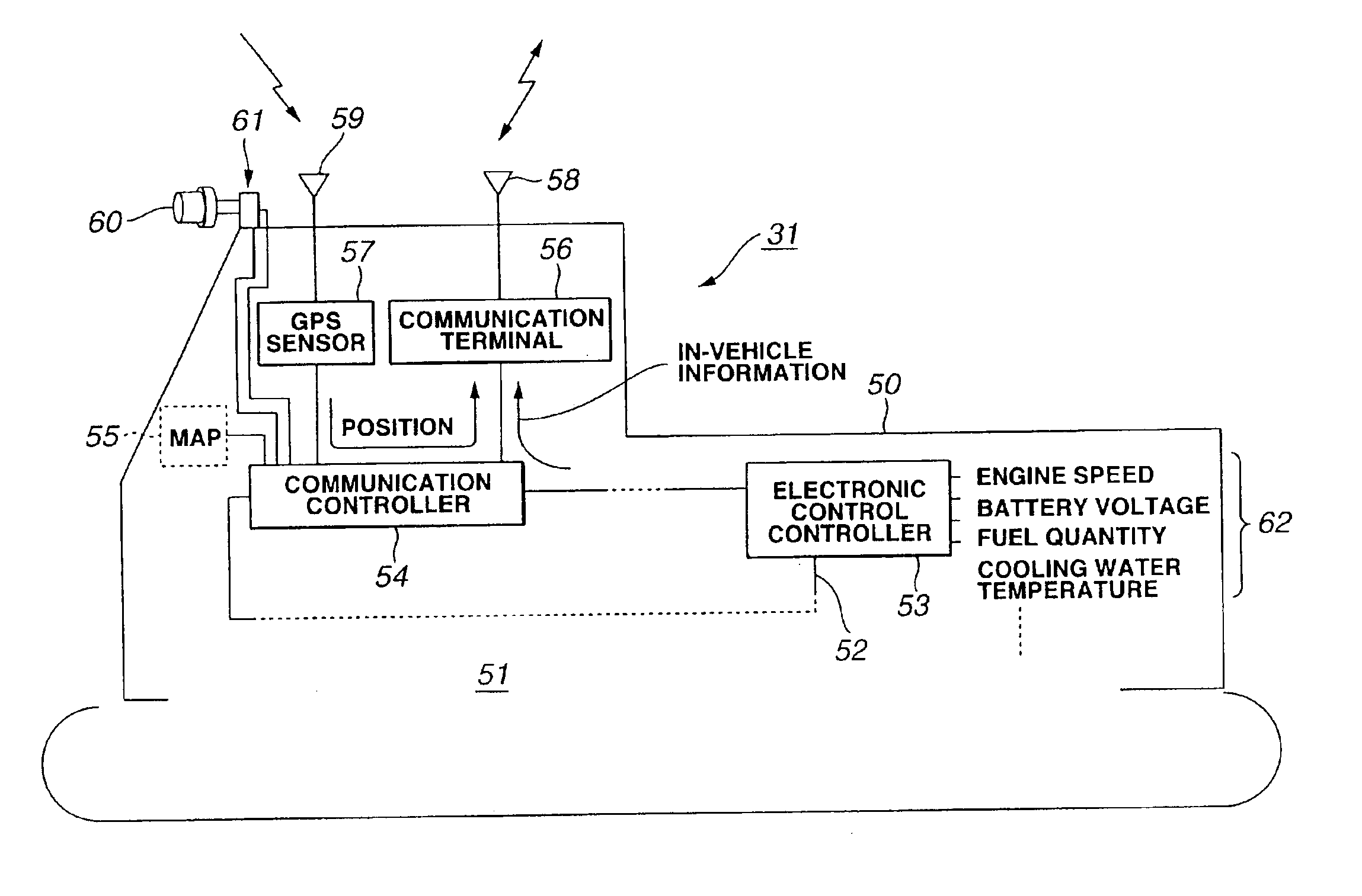
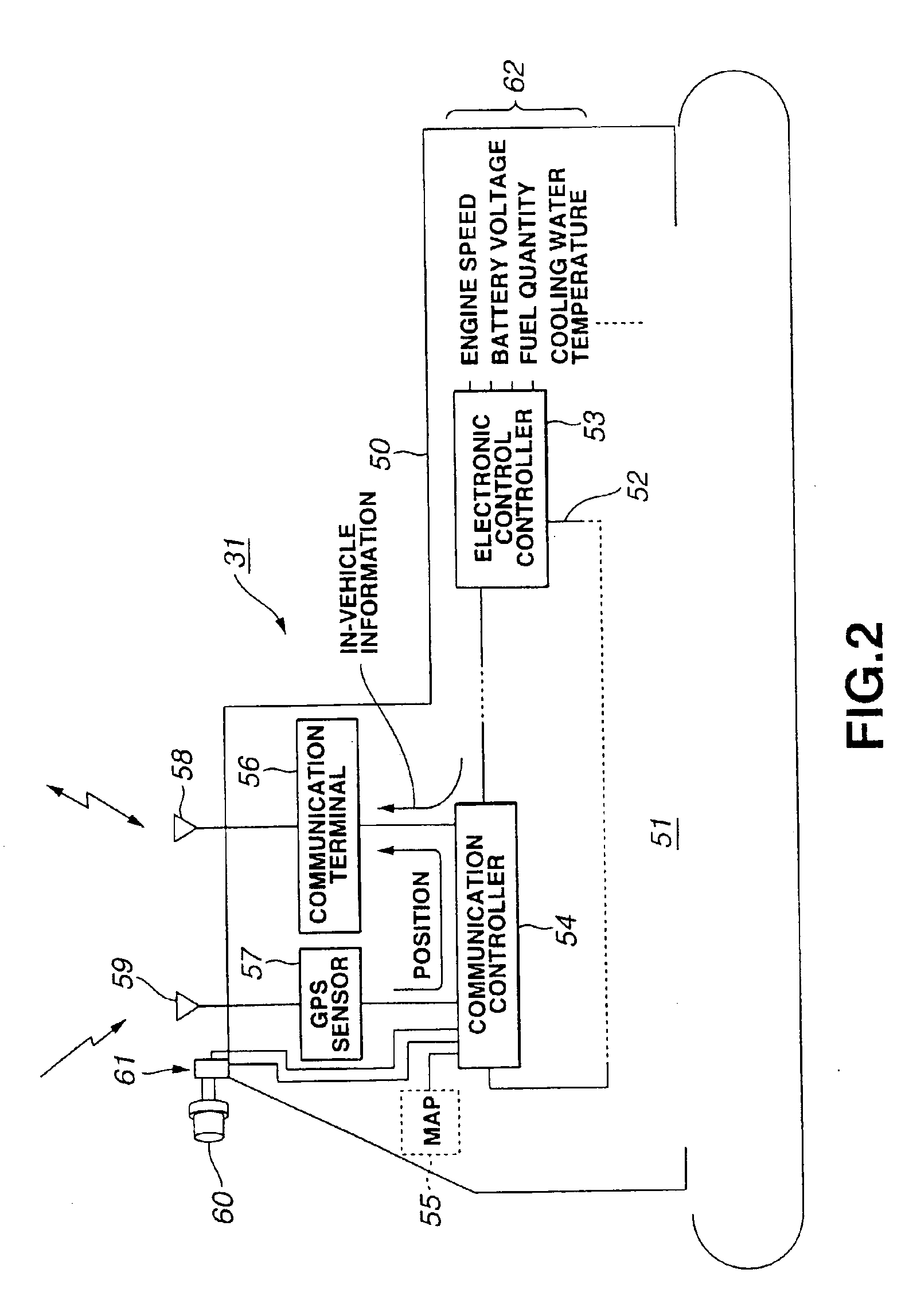
It is assumed that a monitoring panel is provided in the operating cab of the construction machines 31, 32. An operating switch group comprising a display screen and various operating switches is disposed on the outer face of the monitoring panel. When a sensor detection value detected by the sensor group 62 in the construction machines 31, 32 reaches an abnormal value, a caution mark is illuminated on the display screen of the monitoring panel. When an error code is generated in the interi...

second embodiment

(Second Embodiment)

The second embodiment will be described with reference to FIG. 43. In this second embodiment, the terminal 11 is provided on the side of an administrator who manages a plurality of service persons.

FIG. 43 illustrates the display content of a display screen on the terminal 11 display device.

In this second embodiment, a case is envisaged in which inspections, repairs and the like of five construction machines 31, 32, 33, 36, 37 are performed by three service persons.

An identical monitoring panel to the first embodiment is provided in the operating cabs of the construction machines 31, 32, 33, 36, 37.

The operating switch group on the monitoring panel comprises a service person ID input switch for inputting service person ID data. Here, service person ID indicates a combination of numerals, characters, symbols, and codes which is allocated to each individual service person to identify one service person from another.

In this second embodiment, the service person ID of ...

third embodiment

(Third Embodiment)

The third embodiment will be described with reference to FIG. 44. In this third embodiment, the terminal 11 is provided on the side of an administrator who manages a plurality of construction machines in a rental company, for example.

FIG. 44 illustrates the display content of a display screen on the terminal 11 display device.

In this third embodiment, a case is envisaged in which attachment switching work for four construction machines 31, 32, 33, 36 is performed by three service persons.

It is assumed that an identical monitoring panel to the first and second embodiments is provided in the operating cabs of the construction machines 31, 32, 33, 36.

An operating switch group on the monitoring panel comprises a service person ID input switch for inputting service person ID data, and an attachment ID input switch for inputting attachment ID data. Here, service person ID indicates a combination of numerals, characters, symbols, and codes which is allocated to each indiv...


PUM


Abstract

An object of the present invention is to ensure that the amount of time a construction machine has been operated by each operator can be managed. A further object is to ensure that an administrator can learn without delay, in real time, and accurately that a service person has performed services on a construction machine, and to ensure that work instructions are imparted to a service person, and service person performance management and labor management are performed easily and accurately. Another object is to ensure that the attachment situation of a construction machine can be learned accurately and in real time such that customer requests can be dealt with promptly. Another object is to ensure that communication messages can be displayed on the limited space of a monitoring panel display screen together with information which is necessary for driving. When driver identification data (operator ID “010A”) for identifying a driver A is inputted at the operating start time of a work machine 31 (vehicle ID “CAR001”), the inputted driver identification data (operator ID “010A”), the operating time of the construction machine 31 (“2 hours and 15 minutes”), and the time and date (“6:00, May 21”) at which the driver identification data (operator ID “010A”) was inputted are transmitted from the work machine 31 to a terminal device 11. As a result, the amount of time the construction machine 31 was operated by the driver A is displayed on the terminal 11, and the work machine 31 can be managed on the basis of this display content.

Description

BACKGROUND OF THE INVENTION1. Field of the InventionThe present invention relates to a device for managing work machines such as construction machines.2. Description of the Related ArtA construction machine is installed with a service meter, and by reading the value of this service meter, the amount of time one construction machine has been in operation can be learned.However, one construction machine is often used alternately by a plurality of operators. Hence, by simply reading the service meter, the extent to which each operator has operated the construction machine cannot be learned.Thus, a first problem to be solved by the present invention is to enable management of the amounts of time each operator has operated a construction machine.An administrator for managing construction machinery dispatches a service person to the location of a construction machine either periodically or whenever a request is received from a user (operator), and this service person performs services suc...

Claims


Application Information

Patent Timeline
IPC IPC(8): E02F9/26E02F9/20G07C5/00G07C5/08H04B7/185
CPCE02F9/2025E02F9/26H04B7/1851G07C5/085G07C5/008E02F9/2054E02F9/267
Inventor ARAKAWA, SHUJIKAMADA, SEIJI
Owner KOMATSU LTD
Why Eureka
Try Eureka