Method and apparatus for implementing projections in signal processing applications

a signal processing and projection technology, applied in the direction of orthogonal multiplex, multiplex communication, instruments, etc., can solve the problems of complexity of the receiver, interference of signals from the other source, and complexity of the receiver

Inactive Publication Date: 2005-02-15
III HLDG 1
View PDF58 Cites 16 Cited by
  • Summary
  • Abstract
  • Description
  • Claims
  • Application Information

AI Technical Summary

Benefits of technology

It is therefore an object of the present invention to provide a method and apparatus that provide for signal projection computations in signal processing applications without the need for any matrix inversions or square root computations.

Problems solved by technology

However, such receivers are more complex than receivers that distinguish between messages by time and / or frequency alone.
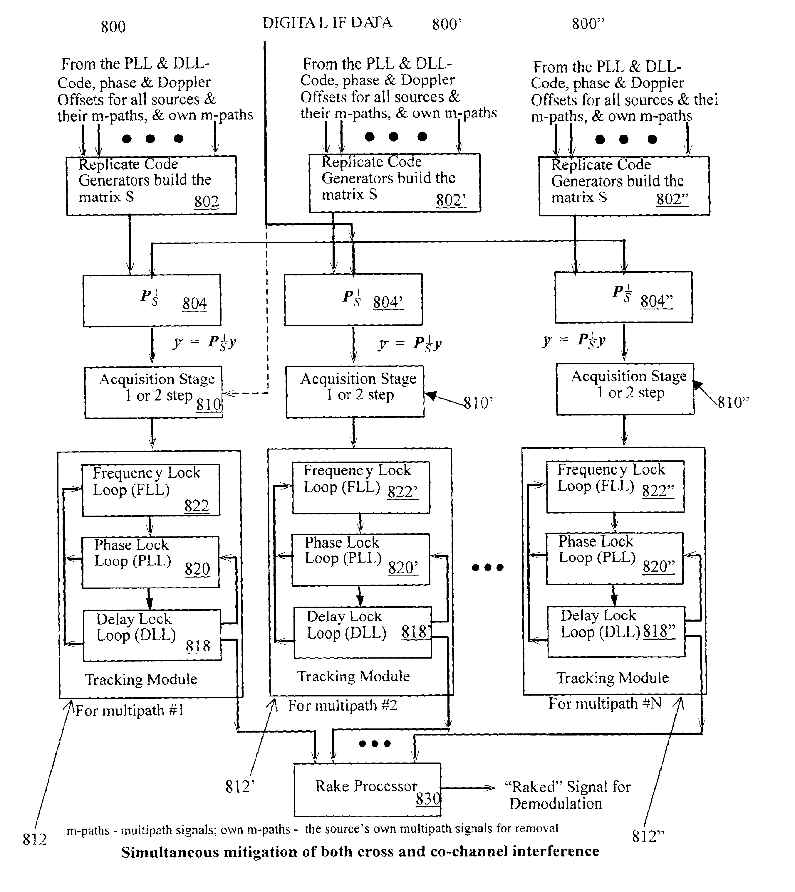
The complexity arises because the signal received by the receiver is a linear combination of all the coded signals present in the spectrum of interest at any given time.
Suppose the receiver is interested in source number 1, the signals from the other sources may be considered to be interference.
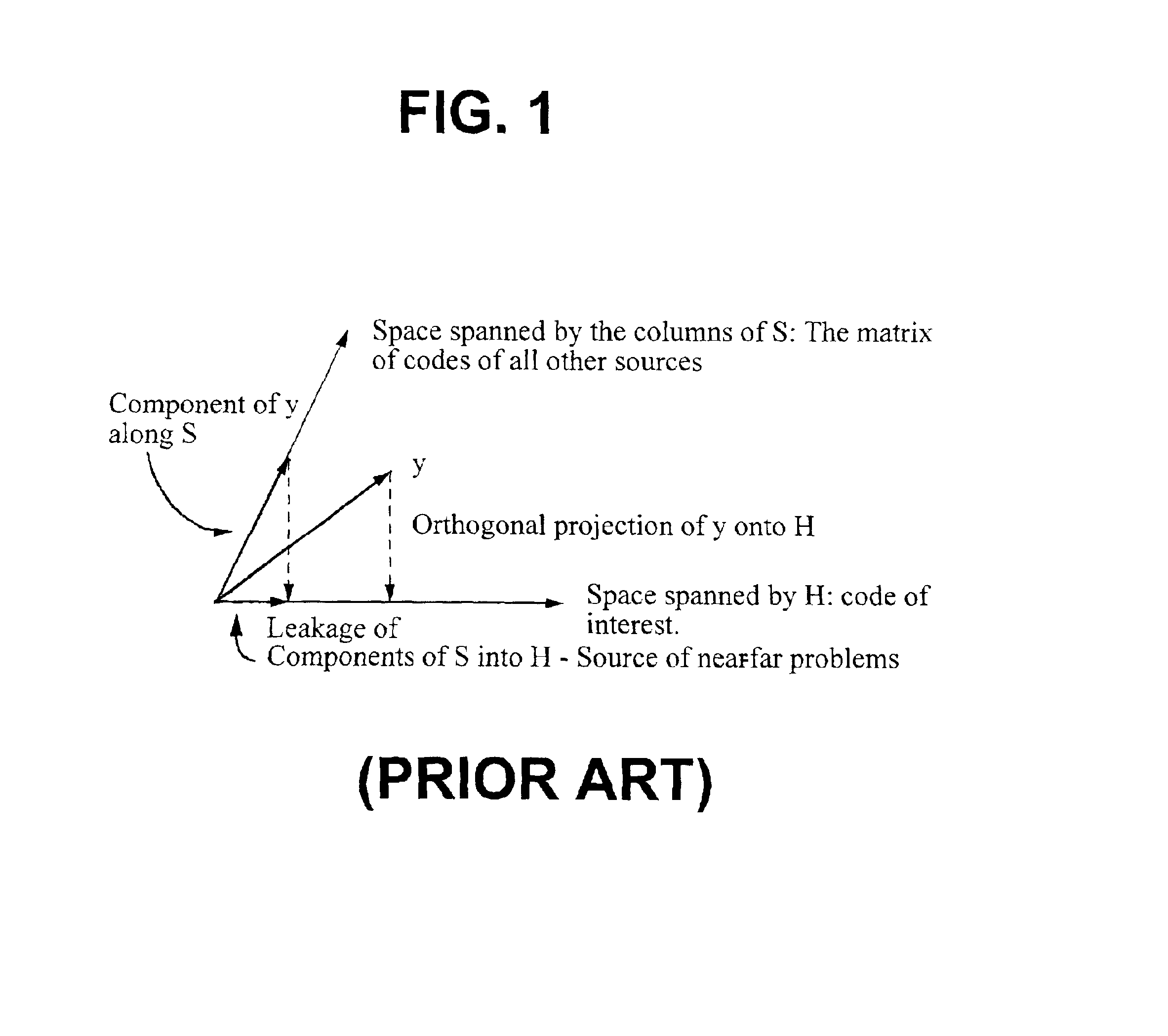
It is the middle term, (HTH)−1HTSφ, in the above equation that results in the near-far problem.
It is easy to see that as the amplitude of the other sources increases, then the term (HTH)−1HTSφ contributes a significant amount to the correlation function, which makes the detection of θ more difficult.
This direct matrix inversion method requires computing the inverse, which may be prohibitive in hardware.
In addition, the direct matrix inversion method cannot handle a subspace matrix S that is singular.

Method used


Image

  • Method and apparatus for implementing projections in signal processing applications
  • Method and apparatus for implementing projections in signal processing applications
  • Method and apparatus for implementing projections in signal processing applications

Examples


Embodiment Construction

It is advantageous to define several terms before describing the invention. It should be appreciated that the following definitions are used throughout this application.

Definitions

Where the definition of terms departs from the commonly used meaning of the term, applicant intends to utilize the definitions provided below, unless specifically indicated.

For the purposes of the present invention, the term “analog” refers to any measurable quantity that is continuous in nature.

For the purposes of the present invention, the term “base station” refers to a transmitter and / or receiver that communicate(s) with multiple mobile or stationary units in a cellular environment.

For the purposes of the present invention, the term “baseline receiver” refers to a receiver against which a receiver of the present invention is compared.

For the purposes of the present invention, the terms “basis” and “basis vector” refer to a set of vectors that completely span the space under consideration. In 3-D space,...


PUM


Abstract

A novel method and apparatus is provided for enabling the computation of a signal in a certain subspace, its projection that lies outside the subspace, and the orthogonal basis for a given matrix. More particularly, the present invention relates to the use of such a method or apparatus for real-time hardware applications since the method and apparatus may be utilized without matrix inversions or square root computations.

Description

BACKGROUND OF THE INVENTION1. Field of the InventionThe present invention relates generally to a method and apparatus that enables the computation of a signal in a certain subspace, its projection that lies outside the subspace, and the orthogonal basis for a given matrix. More particularly, the present invention relates to the use of such a method or apparatus for real-time hardware applications since the method and apparatus may be utilized without matrix inversions or square root computations.2. Description of the Prior ArtIn spread spectrum systems, whether it is a communication system, a Global Positioning System (GPS) or a radar system, each transmitter may be assigned a unique code and in many instances each transmission from a transmitter is assigned a unique code. The code is nothing more than a sequence (often pseudorandom) of bits. Examples of codes include the Gold codes (used in GPS—see Kaplan, Elliot D., Editor, Understanding GPS: Principles and Applications, Artech Ho...

Claims


Application Information

Patent Timeline
Patent Type & Authority Patents(United States)
IPC IPC(8): G01S1/00H04B1/707G01S19/21G01S19/22H04W88/00
CPCG01S19/21G01S19/22H04B1/7105H04B1/7103H04B2201/70715H04B2001/70706H04B1/7113
Inventor THOMAS, JOHN K.NARAYAN, ANAND P.
Owner III HLDG 1
Why Eureka
Try Eureka