Multiprocessor system and method for simultaneously placing all processors into debug mode

a multi-processor computer and debug mode technology, applied in the field of multi-processor computer systems, can solve the problems of inability to probe the state of the processors, inability to use the state extracted from these processors in the determination of the cause of the unexpected debug event, and inability to synchronize the debug events of the different processors of the multi-processor system

Inactive Publication Date: 2005-02-15
AVAGO TECH INT SALES PTE LTD
View PDF2 Cites 55 Cited by
  • Summary
  • Abstract
  • Description
  • Claims
  • Application Information

AI Technical Summary

Problems solved by technology

However, most debug events incurred by the different processors of a multiprocessor system are generally unsynchronized and independent of each other.
By the time that all processors have been stopped, the state of the processors will have advanced to the point that the use of the state extracted from these processors in the determination of the cause of the unexpected debug event is no longer valid.
Consequently, it is extremely difficult or impossible to probe the state of the processors in order to evaluate the cause and effect of the debug event.
However, halting the other processors under control of the debug monitor program when one processor enters the debug mode may result in an excessive time delay before the other processors of the multiprocessor system can halt execution of their program instructions.
During this time delay, the continued execution of the program instructions by the other processors does not adequately preserve, for debugging purposes, the state of the other processors at the time of the debug event.
The inability to preserve the state of all of the processors may inhibit, prevent or delay the determination of those conditions which caused the debug event to occur.
Such impediments may greatly complicate the task of debugging a multiprocessor system.

Method used


Image

  • Multiprocessor system and method for simultaneously placing all processors into debug mode
  • Multiprocessor system and method for simultaneously placing all processors into debug mode
  • Multiprocessor system and method for simultaneously placing all processors into debug mode

Examples


Embodiment Construction

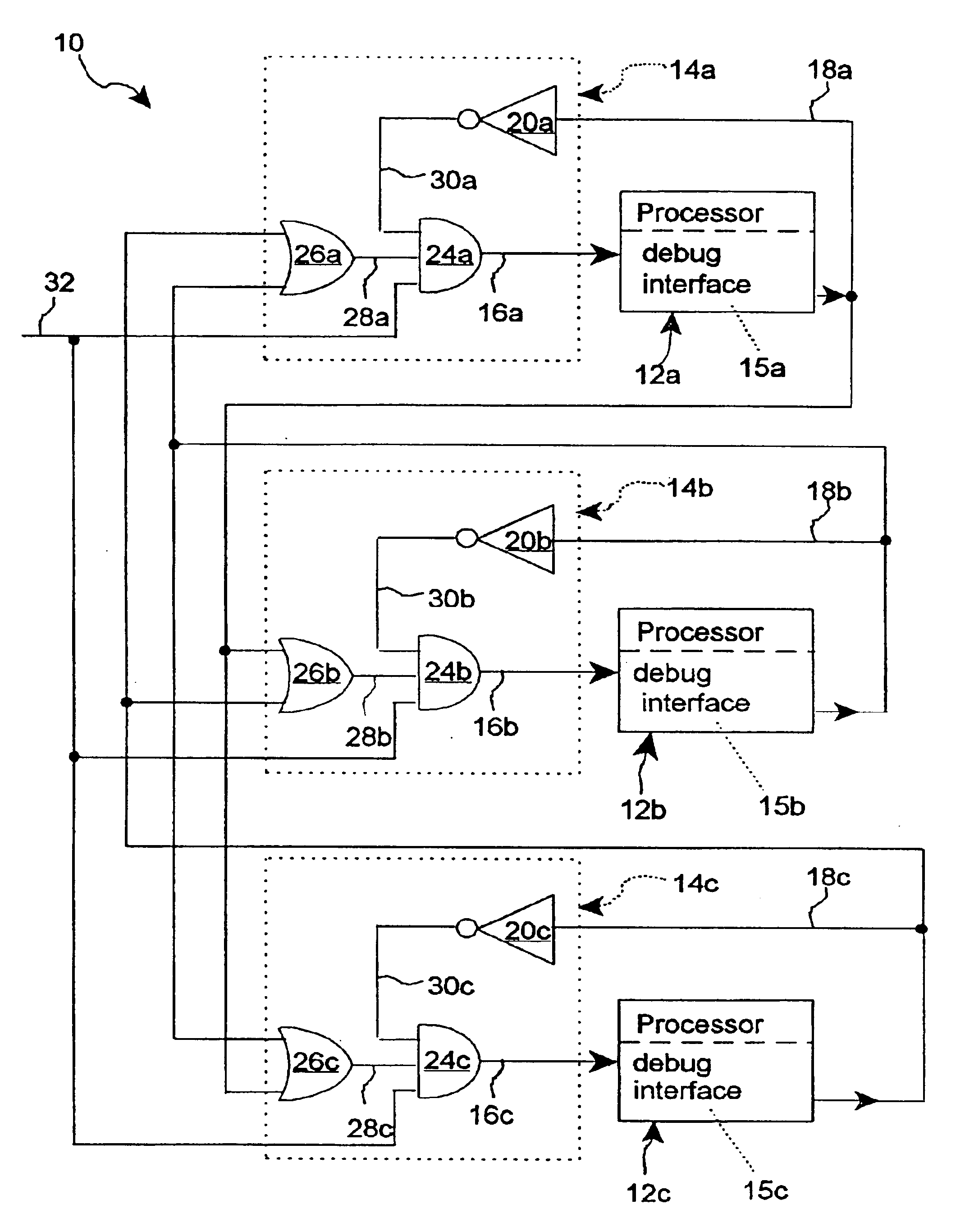
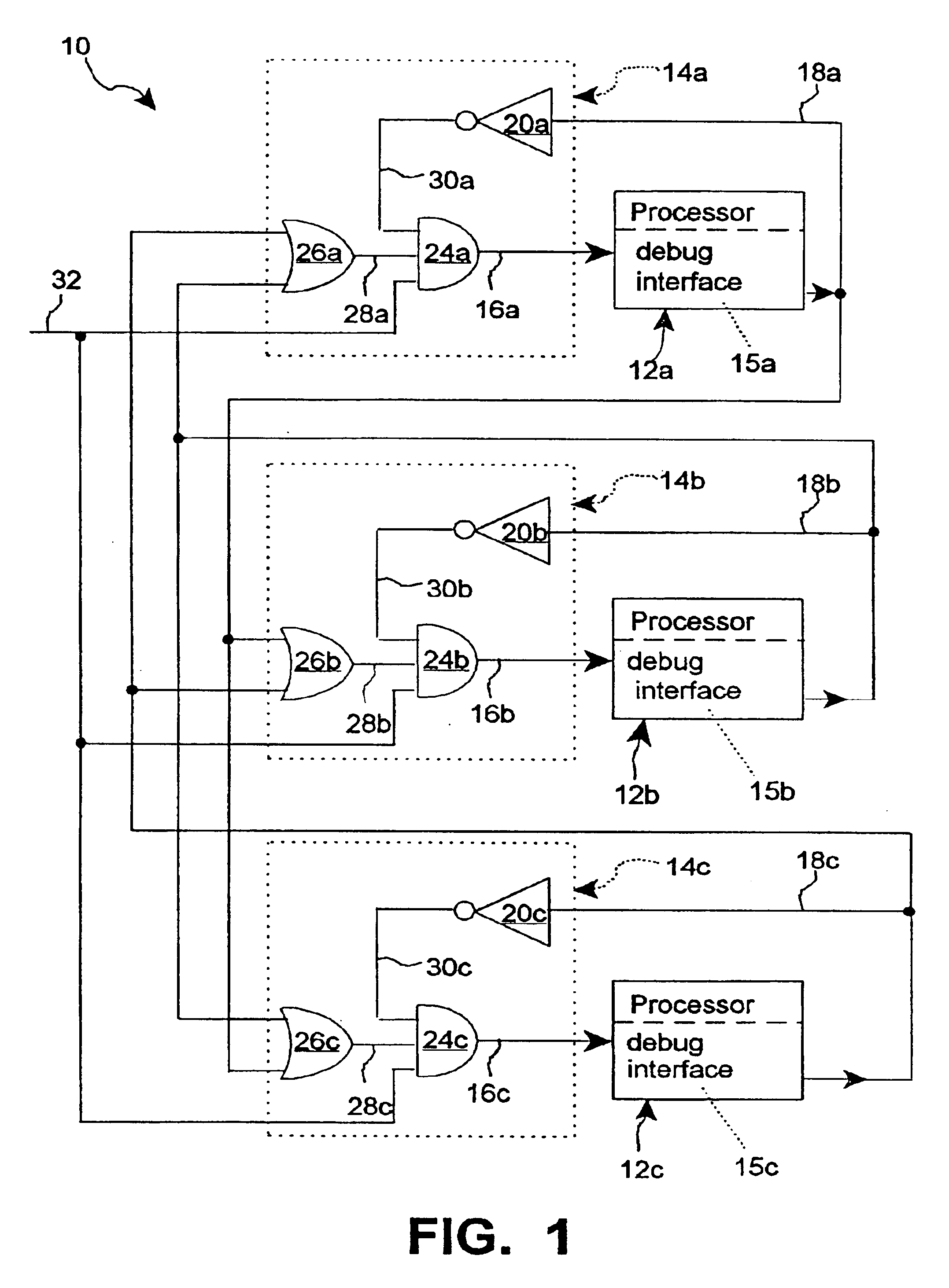
A portion of a multiprocessor system 10 which incorporates and implements the present invention is shown in FIG. 1. The microprocessor system 10 includes a plurality of processors 12a, 12b and 12c, each of which are connected to a plurality of associated external logic circuits 14a, 14b and 14c, respectively. A debug interface circuit 15a, 15b and 15c of each of the processors 12a, 12b and 12c connects the external logic circuits 14a, 14b and 14c to the processors 12a, 12b and 12c, respectively. Although three processors 12a, 12b and 12c are shown in FIG. 1, multiple processors, each with a debug interface circuit connected to an associated external logic circuit, can be included in the same manner as in the multiprocessor system 10. The multiprocessor system 10 may be part of a conventional computer, or the multiprocessor system 10 may be part of a specific device having dedicated functionality, for example a communications interface device.

The debug interface circuit 15a, 15b and ...


PUM


Abstract

Multiple processors of a multiprocessor system are placed into a debug mode of operation approximately simultaneously when one processor initially enters the debug mode as a result of incurring a debug event. The other processors enter the debug mode as a result of the one processor asserting a debug event signal upon initially entering the debug mode. A logic circuit associated with each processor responds to any debug event signal asserted by another processor and the failure of its associated processor to assert a debug event signal, to assert an external debug break signal to the associated processor and place the associated processor into the debug mode.

Description

This invention relates to debugging multiprocessor systems, such as those which may be used in a computer system or in a specific device having dedicated functionality, such as a communications interface. More particularly, the present invention relates to a new and improved circuit and method of placing all processors of a multiprocessor system into a debug mode of operation approximately simultaneously when any one of the processors enters the debug mode.BACKGROUND OF THE INVENTIONIn a multiprocessor computer system, a processor is placed into the debug mode of operation by halting its execution of programmed instructions. The processor then resolves internal conflicts, enters a steady state, and goes into the debug mode. A debug monitor program executes on the processor while the processor is in the debug mode to provide access to the internal resources of the processor. The internal resources of the processor may then be examined to debug the program or the processor hardware. T...

Claims


Application Information

Patent Timeline
Patent Type & Authority Patents(United States)
IPC IPC(8): G06F11/30G06F11/36
CPCG06F11/3648
Inventor GILES, CHRISTOPHER M.
Owner AVAGO TECH INT SALES PTE LTD
Why Eureka
Try Eureka