
Vehicle crash barrier

a technology of crash barriers and vehicles, applied in the direction of doors/window fittings, constructions, ways, etc., can solve the problems of difficult refurbishment, difficult production and maintenance of gates, and the damage of existing products to components other than expendable gates

Inactive Publication Date: 2005-02-22
AUTOMATIC POWER
View PDF11 Cites 26 Cited by
  • Summary
  • Abstract
  • Description
  • Claims
  • Application Information

AI Technical Summary

Benefits of technology

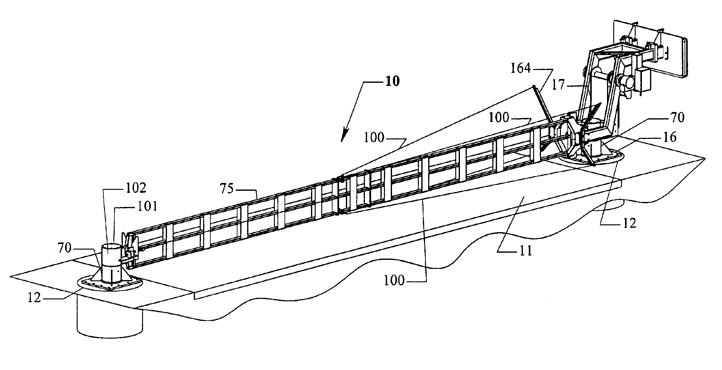
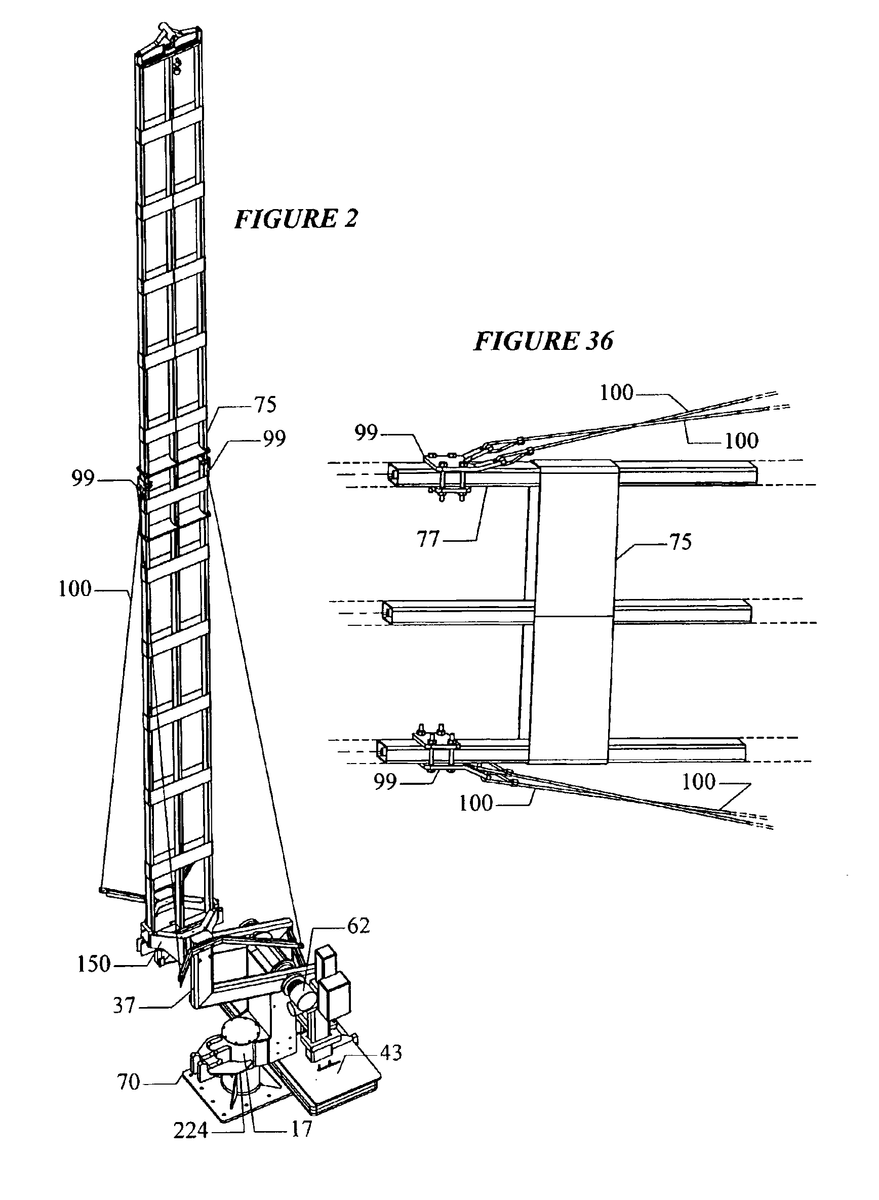
The present invention is a pivoting crash barrier for arresting an impacting vehicle without causing excessive injury to the driver. The crash barrier has an easily replaceable expendable gate which houses multiple plastically extensible cables mounted within for absorbing the energy of the impacting vehicle. The crash barrier gate is pivotally supported to rotate in a vertical plane on a horizontal shaft by an operator unit positioned on a first side of a roadway and an engagement stanchion engageable by the outer tip of the lowered gate on the second, opposed side of the roadway. The crash barrier has an improved latch on the second side of the roadway that prevents inadvertent gate unlatching due to a vehicle imparting uplift to the gate.
The crash barrier has a simplified construction that serves to cause the cables to deform as a unit, rather than separately. Additionally, the heads of the upper sections of the crash barrier stanchions on both sides can pivot about the vertical axes of their respective mounting posts after the shearing of restraining shear pins whenever a vehicle impact occurs. This swiveling reduces the tendency for the components of the crash barrier, other than the gate, to sustain significant damage during vehicle impacts. A further feature of the present invention is a readily adjustable arrangement of the counterweights to bring the rotating components of the crash barrier into substantial balance.

Problems solved by technology

The existing products typically sustain damage to components other than their expendable gates, such as their anchorages, during major impacts.
Furthermore, some of the existing gates, such as the gate shown in U.S. Pat. No. 4,844,653 issued to Dickinson may inadvertently permit a vehicle to escape under the cable when a low-slung vehicle imparts upward motion to the gate during an impact.
Another problem, inherent in the design of the crash gates that are currently available, is that the gates are difficult to produce and difficult to refurbish after undergoing impact.
This complex design makes the Allardyce gate difficult to assemble.
Additionally, damage to the structure other than the gate is likely, making the unit difficult to refurbish after impact.

Method used


Image

  • Vehicle crash barrier
  • Vehicle crash barrier
  • Vehicle crash barrier

Examples


Embodiment Construction

The present invention is directed to a pivoting crash barrier for arresting an impacting vehicle without causing excessive injury to the driver. In particular, the present invention is directed to a crash barrier having an easily replaceable expendable gate that houses multiple plastically extensible metal cables for absorbing the energy of the impacting vehicle.

The crash barrier gate is pivotally supported to rotate in a vertical plane on a horizontal shaft by an operator unit positioned on a first side of a roadway and an engagement stanchion engageable by the outer tip of the lowered gate on the second, opposed side of the roadway. The crash barrier has an improved latch on the second side of the roadway that prevents inadvertent gate unlatching due to a vehicle imparting uplift to the gate.

The crash barrier also has a simplified construction that serves to cause the cables to deform as a unit, rather than separately. Additionally, the heads of the upper sections of the crash bar...


PUM


Abstract

The present invention is a pivoting crash barrier for arresting an impacting vehicle without causing excessive injury to the driver. The crash barrier has an easily replaceable expendable gate which houses multiple plastically deformable cables mounted within for absorbing the energy of the impacting vehicle. The crash barrier design causes the cables to deform as an unit, rather than separately. The crash barrier gate is pivotally supported on a horizontal shaft by an operator unit positioned on a first side of a roadway. An engagement stanchion engageable by the outer tip of the lowered gate supports the lowered gate on the second, opposed side of the roadway. The upper sections of both crash barrier stanchions consist of operator heads that can pivot about the vertical axes of their respective mounting posts after the shearing of restraining shear pins whenever a vehicle impact occurs. This swiveling reduces the tendency for the components of the crash barrier other than the gate to sustain significant damage during vehicle impacts. The crash barrier gate further has a latch on the engagement stanchion side that prevents inadvertent gate unlatching from uplift forces to the gate and a simplified method of balancing the crash barrier with counterweights.

Description

BACKGROUND OF THE INVENTION1. Field of the InventionThe present invention is directed to a pivoting crash barrier for arresting an impacting vehicle without causing excessive injury to the driver. In particular, the present invention is directed to a crash barrier having an easily replaceable expendable gate which houses multiple plastically extensible cables mounted within for absorbing the energy of the impacting vehicle.2. Description of the Related ArtSeveral types of crash barriers have been patented and manufactured historically. These gates rely upon supporting plastically deformable cables between anchorages on both sides of the roadway in order to establish a readily removable and insertable barrier, which can absorb impact energy through yielding of the cables. The existing products typically sustain damage to components other than their expendable gates, such as their anchorages, during major impacts.Furthermore, some of the existing gates, such as the gate shown in U.S. ...

Claims


Application Information

Patent Timeline
IPC IPC(8): E01F13/06E01F13/02E01F13/00
CPCE01F13/06
Inventor RUSSELL, LARRY R.
Owner AUTOMATIC POWER
Learn More