

Cooler and method of cooling a medium
a technology of cooling medium and cooler, which is applied in the field of cooler, can solve the problems of increasing requiring an enlarged construction space, etc., and achieves the effect of preventing adverse effects and avoiding an increase in the pressure drop inside the cooler
- Summary
- Abstract
- Description
- Claims
- Application Information
AI Technical Summary
Benefits of technology
Problems solved by technology
Method used
Image

Examples
first embodiment
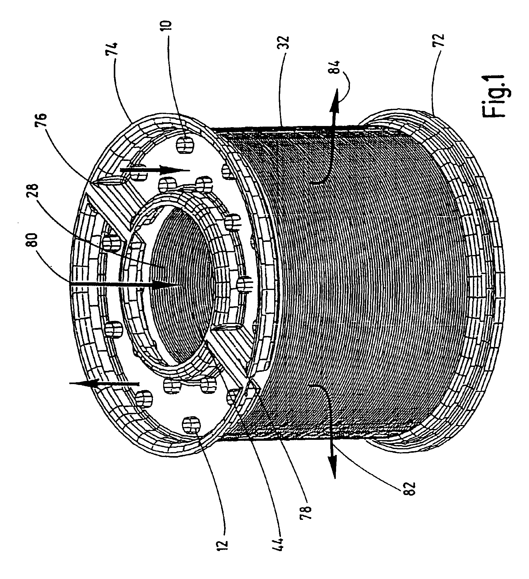
FIG. 1 shows a cooler according to the invention in perspective representation. The cooler has a multiplicity of baffle plates 32 which are arranged in layers one above the other and expose an opening 44 in an inner region as means 28 for directing a medium to be cooled. The cooler is defined on the underside by a coolant box or tank 72. A tank 74 is provided on the top side. The interior of the top tank 74 is provided with two separating elements 76, 78. Cooling medium is directed into the right-hand part of the tank 74. Cooling medium is extracted from the left-hand part of the tank 74. From the right-hand part of the tank 74, the cooling medium passes into the openings 10 which continue in the axial direction through the cooler in the form of tubes. From tubes 12, which likewise continue in the axial direction through the cooler, the heated cooling medium passes into the left-hand part of the tank 74. The bottom tank 72 is designed in such a way that the cooling medium is deliver...
second embodiment
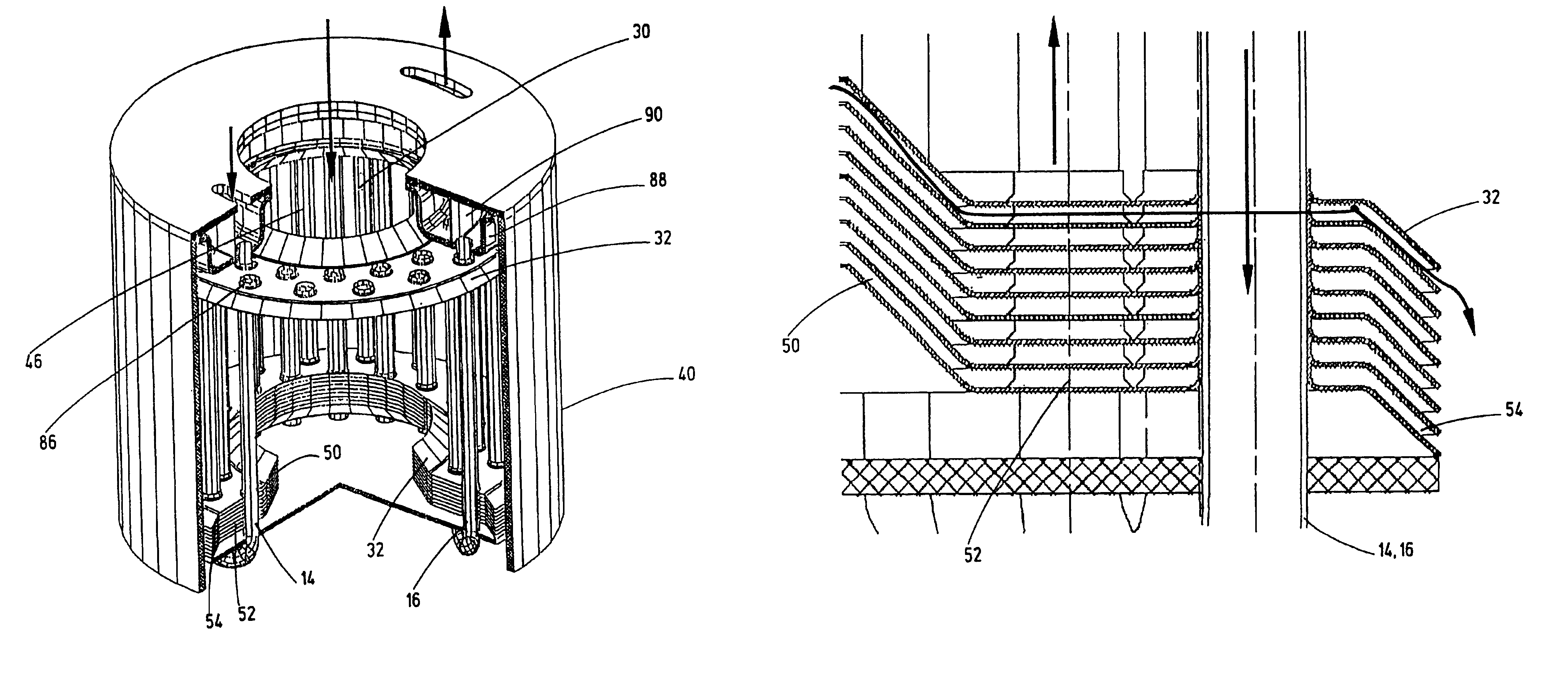
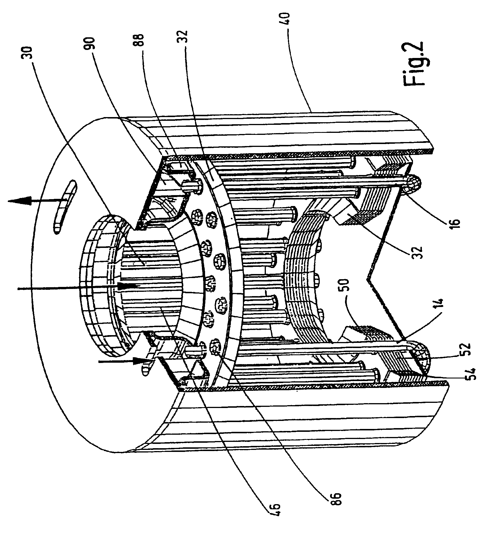
FIG. 2 shows a partly cutaway second embodiment of a cooler according to the invention in perspective representation. The cooler according to FIG. 2 may be provided with baffle plates 32 over its entire inner axial length, although, for the sake of clarity, only some baffle plates 32 arranged in the bottom region and one baffle plate 32 arranged in the top region are shown in this case. The cooler is surrounded by a housing 40. Arranged in the top region of the housing is a tank 88 which has a partition 90 running in the circumferential direction. Cooling medium is directed into the radially inner part of the tank 88, and cooling medium is extracted from the radially outer part of the tank 88. The cooling medium directed into the tank passes through the tubes 14, which extend axially downward into the cooler, into the region of the baffle plates 32. The tubes 14 are curved in the bottom region, and they merge into the part of the tubes which is identified by the reference numeral 16...
third embodiment
FIG. 8 shows a partly cutaway third embodiment of a cooler according to the invention in perspective representation. In this embodiment of a cooler according to the invention, a multiplicity of disks 70 are arranged inside a housing 42. One of these disks is shown individually in FIG. 10. Cooling liquid can be directed into the cooler through an opening 18. This cooling liquid then passes into a passage 24 which is formed by openings in the disks 70. The disks are arranged in such a way that passages 22 running in the circumferential direction are formed, which will be explained in more detail below with reference to FIG. 10. The cooling liquid directed into the passage 24 can thus be distributed in the circumferential direction through the passages 22 and can discharge again from the cooler through the opening 20. Cooling fins 36, 38 are arranged between the disks 70, which themselves are arranged in pairs in each case to form a closed passage. Air entering the opening 48, which se...
PUM
 Abstract
Description
Claims
Application Information