Membrane seals

a technology of membrane seals and membranes, applied in the direction of machines/engines, liquid fuel engines, lighting and heating apparatus, etc., can solve the problems of premature wear and thermal attrition of the first and second sealing members, and achieve the effect of reducing fluid leakag

Inactive Publication Date: 2005-02-22
ANSALDO ENERGIA IP UK LTD
View PDF8 Cites 23 Cited by
  • Summary
  • Abstract
  • Description
  • Claims
  • Application Information

AI Technical Summary

Benefits of technology

An object of the present invention is therefore to provide a membrane seal that suffers less premature wear and produces a better seal.
Because at least one of the first and second members has an oval cross-section instead of a circular cross-section there is a larger zone of contact between the first and / or second sealing member(s) and the sealing groove(s). This reduces the amount of wear on the first and / or second sealing member(s) but still allows the membrane seal to be easily replaced if necessary. The larger zone of contact creates a better seal by providing a larger sealing area between the first and / or second sealing member(s) and the sealing groove(s).
To reduce fluid leakage through such a membrane seal, each of the membrane seal segments preferably includes a tongue along one of its radial edges and a groove along its other radial edge for receiving the tongue of an adjacent membrane seal segment. Alternatively, each membrane seal segment may include a rebate on one of its radial edges and a complementary rebate on its other radial edge for cooperating with the rebate of an adjacent membrane seal segment.

Problems solved by technology

A major disadvantage with conventional membrane seals is that the first and second sealing members suffer from premature wear and thermal attrition caused by the high levels of vibration encountered in the gas turbine engine.

Method used


Image

  • Membrane seals
  • Membrane seals
  • Membrane seals

Examples


Embodiment Construction

The present invention will now be explained with reference to FIGS. 2 to 4b.

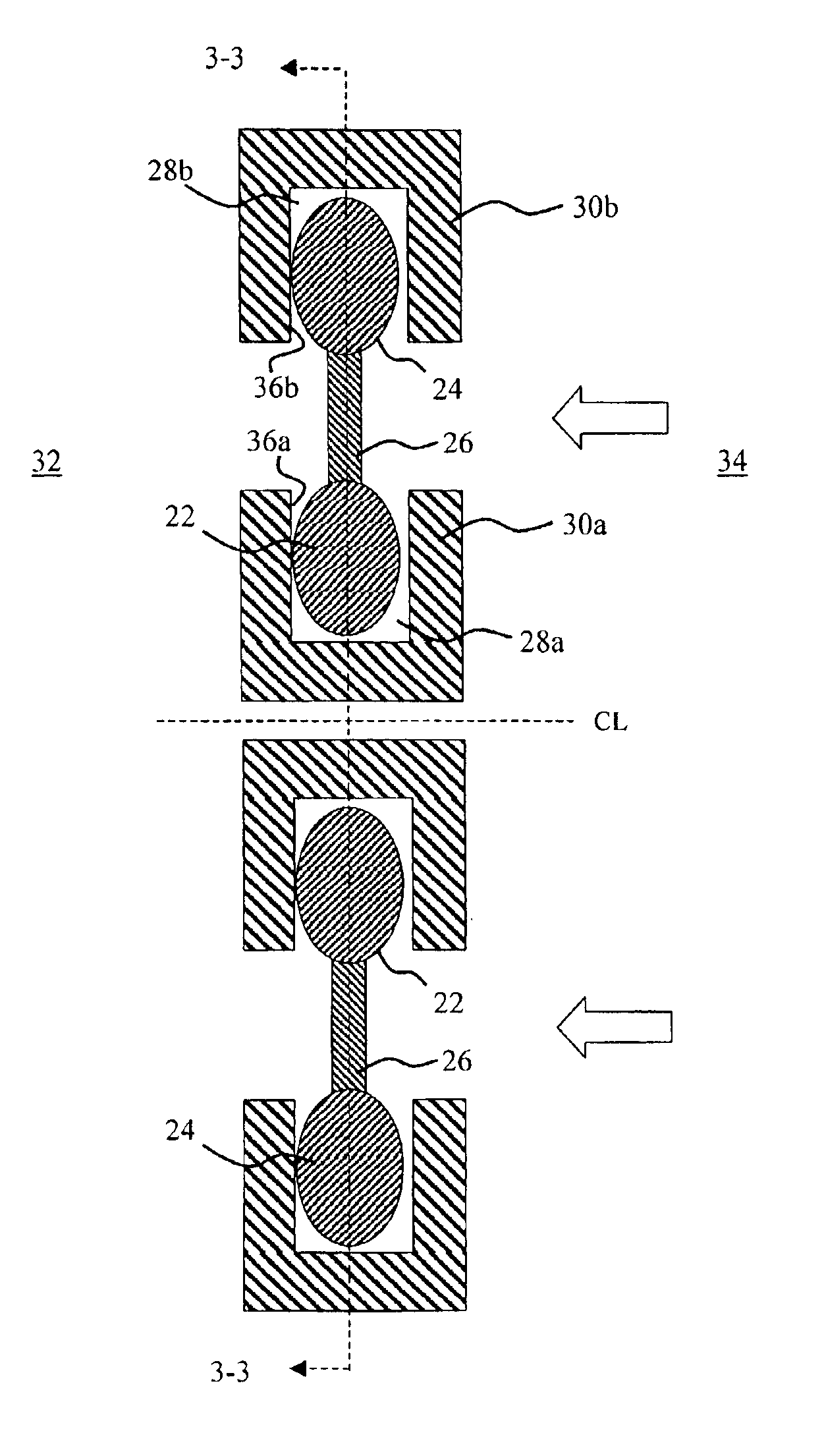
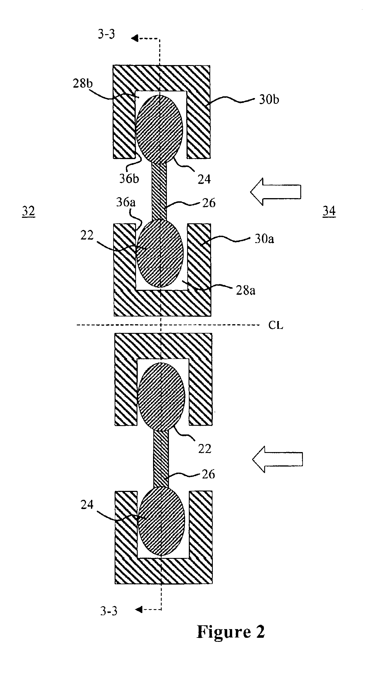
FIG. 2 shows a membrane seal 20 having a first radially inner annular sealing member 22 and a second radially outer annular sealing member 24 sealably connected together by an annular membrane 26. Both the first and second sealing members 22, 24 have an oval cross-section. The first and second sealing members 22, 24 are contained within annular sealing grooves 28a, 28b formed by mutually confronting radially inner and outer tracks 30a, 30b as described above. The two tracks 30a, 30b are mounted on a radially inner and radially outer portion of a gas turbine engine casing (not shown) respectively.

The membrane seal 20 is positioned between a low-pressure region 32 of the engine and a high-pressure region 34 of the engine. The axial width of the sealing grooves 28a, 28b is slightly wider than the axial width of the first and second sealing members 22, 24. This means that the first and second sealing members 22...


PUM


Abstract

A membrane seal includes a pair of confronting annular sealing grooves. A first annular sealing member is received in one of the oppositely facing sealing grooves and a second annular sealing member is received in the other of the oppositely facing sealing grooves. The first and second sealing members are sealably connected together by an annular membrane. A pressure difference across the membrane forces the first and second sealing members into contact with a side wall of each of the oppositely facing sealing grooves to effect a seal. Known sealing members have a circular cross-section but in the present invention at least one of them has an oval cross-section. The oval cross-section gives the first and / or second sealing member(s) a larger zone of contact with the oppositely facing sealing groove(s). This reduces the amount of wear on the first and / or second sealing member(s) and produces a better seal.

Description

BACKGROUND OF THE INVENTION1. Field of the InventionThe present invention relates to membrane seals, and in particular to membrane seals for sealing between high-pressure and low-pressure regions of a gas turbine engine or jet engine.2. Description of the Related ArtThe background art will be explained with reference to FIG. 1. Membrane seals are a common way of providing a fluid-tight seal between different pressure regions and are typically found in gas turbine engines and jet engines. Membrane seals of the type with which the present invention is concerned include a first radially inner annular sealing member 2 and a second radially outer annular sealing member 4 sealably connected together by an annular membrane 6. Both the first and second sealing members 2, 4 have a circular cross-section. In FIG. 1 the first and second sealing members 2, 4 are shown to have a solid cross-section but they can be tubular. The first sealing member 2 is contained within an annular sealing groove ...

Claims


Application Information

Patent Timeline
Patent Type & Authority Patents(United States)
IPC IPC(8): F01D11/00F01D25/24F16J15/08
CPCF01D11/005F16J15/0887F01D25/246F05D2240/11
Inventor HIRST, ROBERT
Owner ANSALDO ENERGIA IP UK LTD
Why Eureka
Try Eureka